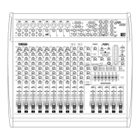
Rear Panel
7
ProMix 01 User’s Guide
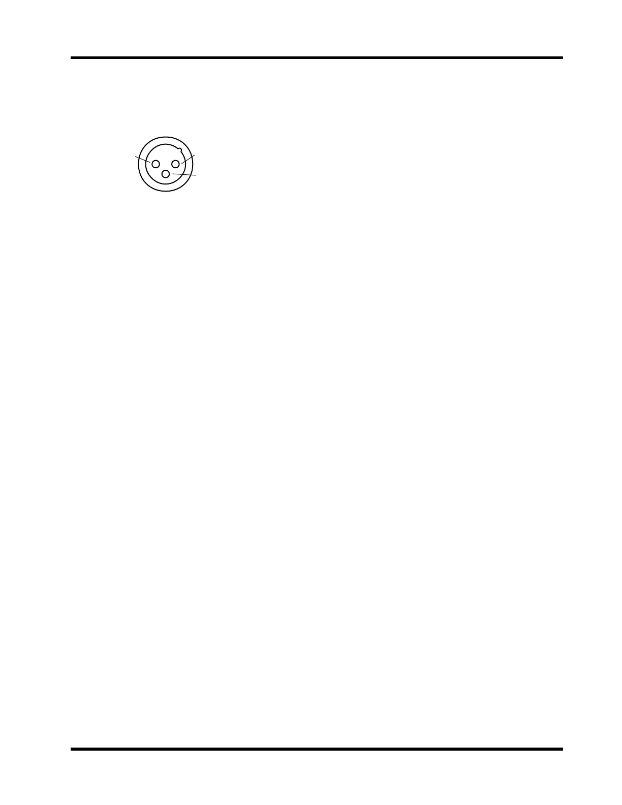
9. STEREO OUT
These are balanced XLR-3-32 type connectors with a +4dB nominal
output level. They are wired pin 1–ground, pin 2–hot (+), and pin
3–cold (–).They output the main stereo signals and can be connected
to power amplifiers in sound reinforcement applications.
10.REC OUT
The ANALOG outputs are RCA/phono jacks with a –10dB nominal
output level. They output the main stereo signals for recording, and
can be connected to cassette and other analog recorders. They can also
be used instead of the XLR STEREO OUTs to connect ProMix 01 to
your home hi-fi system.
The DIGITAL COAXIAL output is an RCA/phono jack. It outputs the
main stereo signals for recording, and can be connected to DAT, MD,
and DCC digital recorders via a 75 ohm coaxial cable. The digital out-
put format is IEC958 (Consumer).
11.MIDI
These are standard MIDI IN and OUT connections. They can be used
to connect a controlling computer or MIDI sequencer for automated
control. They can also be used for control of other ProMix 01s in a
multiple system. See “MIDI” on page 79.
Note:
When the STEREO OUT XLRs are used with unbalanced con-
nectors, their maximum output level is reduced by 6dB. This means that
the STEREO OUT signal actually clips when the 12dB LED lights up,
which is 8dB before the CLIP LED.
1
2
3
Hot
Cold
Ground