Do you have a question about the Yamaha PSR-170 and is the answer not in the manual?
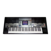
| Type | Portable Keyboard |
|---|---|
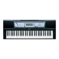
| Keyboard | 61 keys |
| Effects | Reverb, Chorus |
| Polyphony | 32 notes |
| ROM | 100 voices |
| Display | LCD |
| Presets | 100 styles |
| Connections | Headphones |
| Power Supply | AC adapter or batteries |
Information for authorized service personnel, product accuracy, and modification notices.
Warning about lead content in solder and potential health risks from components.
Notice regarding components marked with a symbol and the need for exact replacement.
Details about the keyboard, its keys, and the multi-function LCD display.
Lists panel controls, voice types, effects, auto accompaniment, and song features.
Information on amplifier, power supply, dimensions, weight, and included/optional accessories.
Diagram and identification of controls on the top surface of the instrument.
Diagram and identification of ports and connectors on the rear panel.
Diagram showing the main ICs and memory/driver units (DM-LCD).
Diagram illustrating keyboard matrix, power amp, and I/O interfaces.
Layout of components and connectors on the upper case side of the circuit boards.
Layout of components and connectors on the lower case side.
Steps for removing the lower case assembly, including battery cover and screws.
Procedure for removing the spring terminals and battery connector assembly.
Instructions for removing PN-AM, LCD, VR boards, and speakers.
Procedure for detaching the left and right speakers from the unit.
Detailed steps for removing individual white and black keys from the keyboard.
Instructions for removing the MK-L and MK-H circuit boards after key removal.
Detailed pin assignments and functions for the YMW728-F (GEW12) LSI.
Pin assignments and functions for the DM-LCD IC001.
Block diagram for the S6A0069X10-Q0RJ LCD driver IC (IC006).
Block diagrams for the μPC4570G2 op-amp (IC004) and BA5417 power amp (IC101).
Visual layout of the DM-LCD circuit board, showing component and pattern sides.
Diagram of the PN-AM 1/2 circuit board, focusing on the component side layout.
Diagram of the PN-AM 2/2 circuit board, showing the component side layout.
Diagram of the VR circuit board, showing the component side layout.
Steps for preparing test instruments and entering the diagnostic test program.
Guide to navigating tests, executing them, and understanding OK/NG results.
Details on tests for LCD display, MIDI communication, ROM, and RAM checks.
Table mapping switch names to their corresponding pitch and LCD display indicators.
Chart detailing MIDI messages transmitted and recognized by the instrument.
Information on MIDI control changes, system exclusive, and real-time messages.
Overview of parts list structure, destination abbreviations, and general warnings.
Exploded view of the overall unit assembly and its major parts.
Detailed list of parts for the overall assembly, speakers, and common components.
Listing of parts related to the keyboard assembly, panel switches, knobs, and LCD unit.
List of white keys, black keys, rubber contacts, and felt parts for the keyboard.
Part numbers for MK circuit boards, connectors, and associated components.
Part numbers for main circuit boards and key ICs.
List of various capacitors, resistors, and inductors used in the unit.
Details on carbon resistors, transistors, diodes, and thermistors.
List of connectors, fuses, heat sinks, and other miscellaneous electronic parts.
List of monolithic Mylar capacitors, electrolytic capacitors, and rotary variable resistors.
Details on various connectors, diodes, transistors, and related parts.
Part numbers for connector assemblies, speakers, and associated components.
Part information for the LCD module and the Zener diode.
Diagram illustrating the overall system architecture and signal flow between major blocks.
Details on power supply circuits and connections to speakers, AC adapter, and MIDI ports.