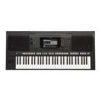
PSR-170
9
9. MK-L and MK-H Circuit Board
(Time required : About 15 min. each)
9-1. Remove the lower case assembly.
(See procedure 1)
9-2. Remove the black and white keys (C1–B3).(See
procedure 8.)
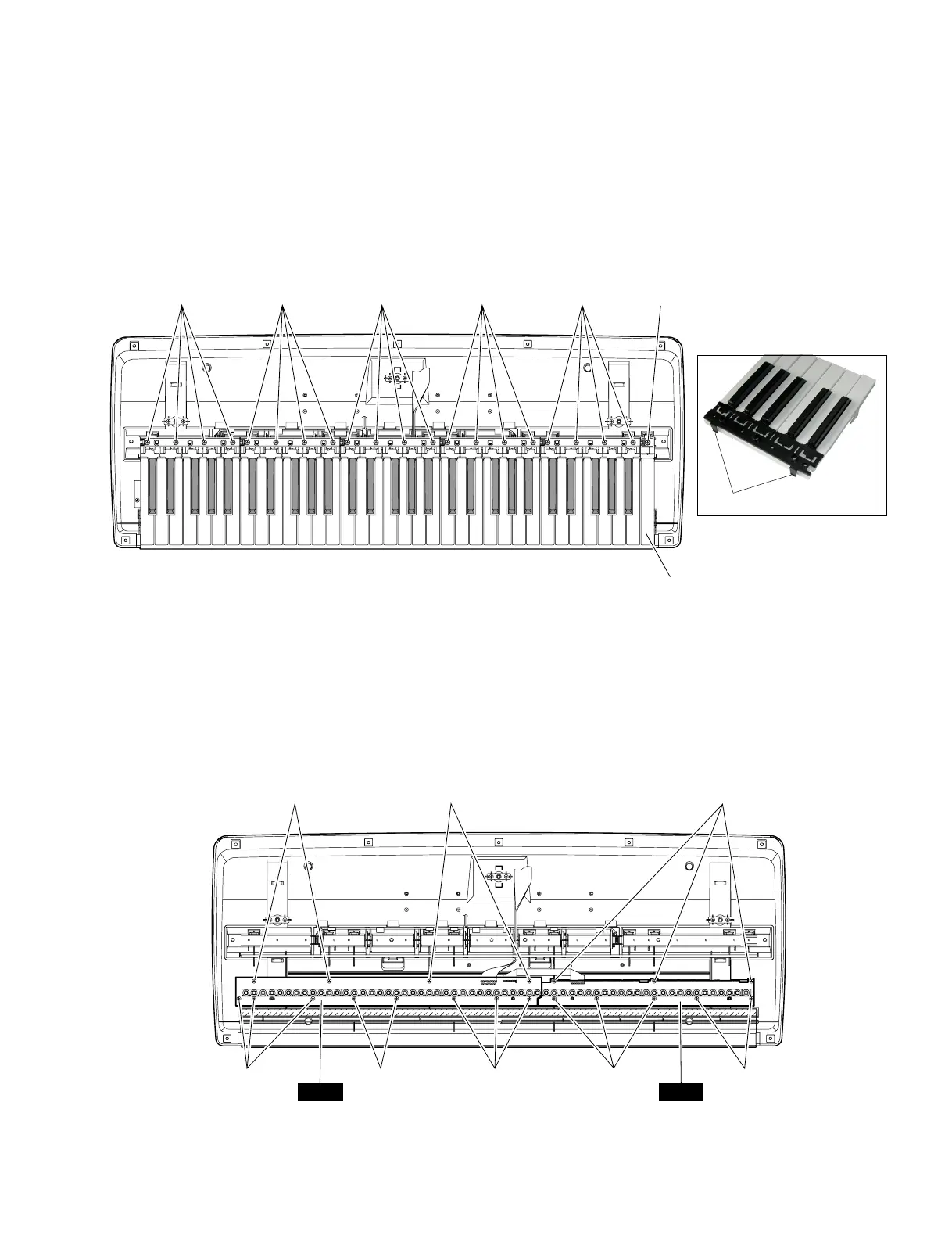
Remove the four (4) screws marked [90A] and the
8. White key and Black key
(Time required : About 10 min. each)
8-1. Remove the lower case assembly.
(See procedure 1)
8-2. Remove the four (4) screws marked [110A] fixing
the black and white keys for one octave. The black
and white keys of each octave can then be removed.
(Fig.7) At this time, lift the back of black key with
[90] : Bind Head Tapping Screw-B 3.0X8 MFZN2Y(EP600250)
[100] : Bind Head Tapping Screw-P SP 3.0X12 MFZNBL(VZ313100)
(Fig. 8)
pushing the hooks of it and slide the black key
towards you. (Photo 1)
8-3. When removing the C6 key, remove a screw
marked [110B] and then lift the back of C6 key
with pushing the hook of it and slide it towards
you. (Fig.7)
eight (8) screws marked [100A]. The MK-L circuit
board can then be removed. (Fig. 8)
9-3. Remove the black and white keys (C4–C6).(See
procedure 8.) Remove the three (3) screws marked
[90B] and the five (5) screws marked [100B]. The
MK-H circuit board can then be removed. (Fig. 8)
[90A]
[100A]
[90A] [90B]
[100A] [100A] [100B] [100B]
MK-L MK-H
[110] : Bind Head Tapping Screw-P 3.0X20 MFZN2 (VT069800)
(Fig. 7)
[110A]
C6 Key
[110A] [110A] [110A] [110A] [110B]
(Photo 1)
Hook
 Loading...