PSR-170
7
■ DISASSEMBLY PROCEDURE
[250] : Bind Head Tapping Screw-B 3.0X12 MFZN2Y (VE683000)
[260] : Bind Head Tapping Screw-B 3.0X30 MFZN2Y (V7213700)
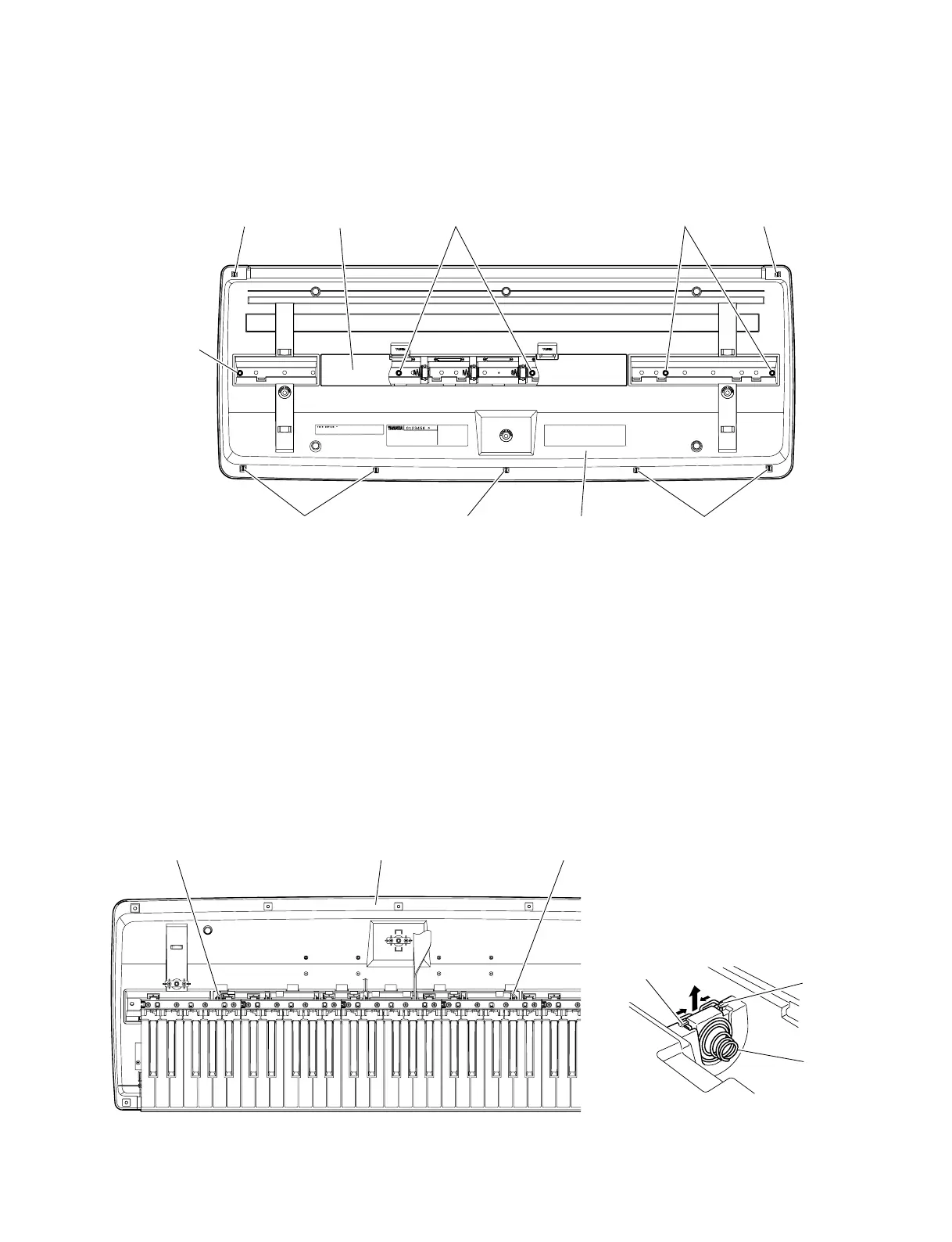
(Fig. 1)
2. Spring Terminal
(Time required : About 10 min.)
2-1. Remove the lower case assembly.
(See procedure 1)
2-2. Remove the BATTERY connector assembly (red/
black) soldered to the spring terminal (+)/(-).
(Fig. 2)
(Fig. 2)
(Fig. 3)
1. Lower Case Assembly
(Time required : About 3 min.)
1-1. Remove the battery cover assembly. (Fig. 1)
1-2. Remove the seven (7) screws marked [250] and
the five (5) screws marked [260]. The lower case
assembly can then be removed. (Fig. 1)
[250] [250]
[250]
[250]
[260] [260]
[250]
Lower Case Assembly
Battery Cover Assembly
[260]
2-3. Remove the spring terminal by releasing hooks (2
locations for each). (Fig. 3)
Spring Terminal
Hook
Hook
Lower Case Assembly
BATTERY Connector
Assembly (Black)
BATTERY Connector
Assembly (Red)
<Top View>
<Bottom View>

 Loading...