ABCDEFGH I JKL
1
2
3
4
5
6
7
8
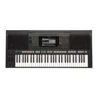
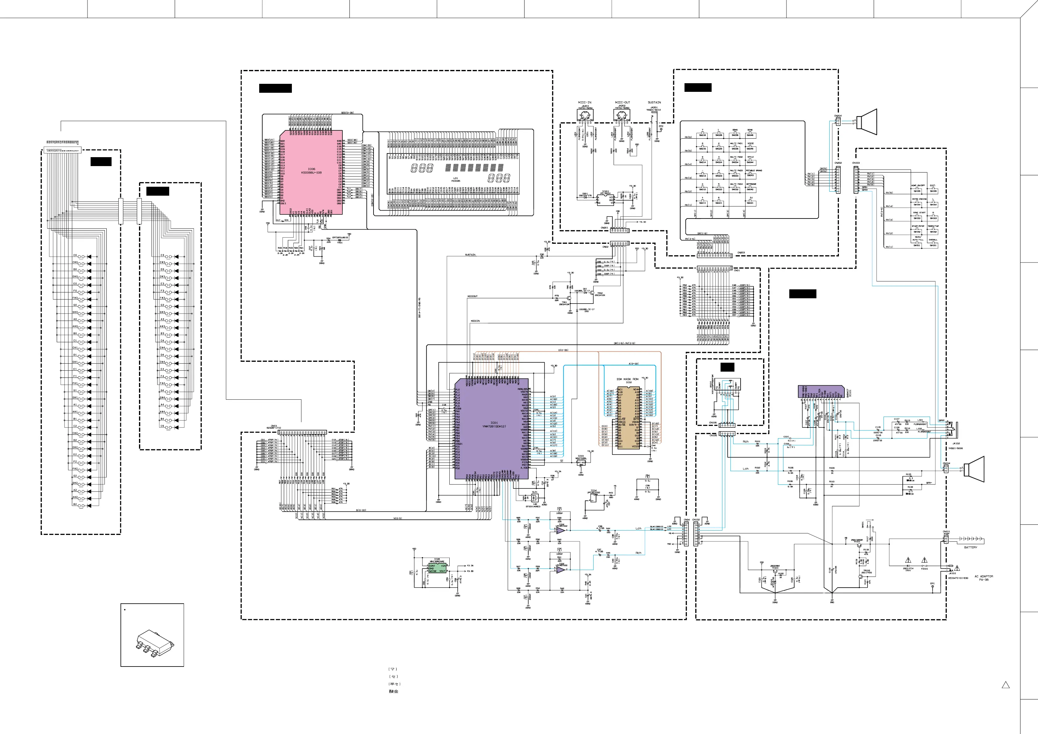
PSR-170
■ PSR-170 OVERALL CIRCUIT DIAGRAM
: Mylar Capacitor
: Ceramic Capacitor
: Semiconductive Ceramic Capacitor
: Metal Oxide Film Resistor
Note : See parts list for details of circuit board component parts.
DM-LCD, PN-AM, VR : 28CC1-8819402
MK-L, MK-H : 28CC1-8819596
WARNING
Components having special characteristics are marked Z and must be replaced with parts having speci-
fication equal to those originally installed.
MK-H
MK-L
DM-LCD
PN-AM
PN-AM
VR
MASTER
VOLUME
PHONES/
OUTPUT
SUSTAINMIDI IN MIDI OUT
STANDBY/ON
DC IN 12V
SPEAKER
L
SPEAKER
R
2/2
1/2
*1
*1: The fuse is soldered.
LCD
POWER AMP
REGULATOR
+5V
REGULATOR
+3.3V
GEW-12
BUFFER
BUFFER
RESET
ROM 16M
PROGRAM STYLE WAVE
MIDI DRIVER
PHOTO
COUPLER
LCD DRIVER
MM1385ENRE (XZ624A00)
REGULATOR +3.3V
CONT
GND
NOISE
VIN
VOUT
5
 Loading...