PSR-170
8
Volume Knob
[L50] : Bind Head Tapping Screw-P 3.0X8 MFZN2Y (EP600280)
(Fig. 5)
5. LCD Unit and DM-LCD Circuit Board
(Time required : About 10 min.)
5-1. Remove the lower case assembly.
(See procedure 1)
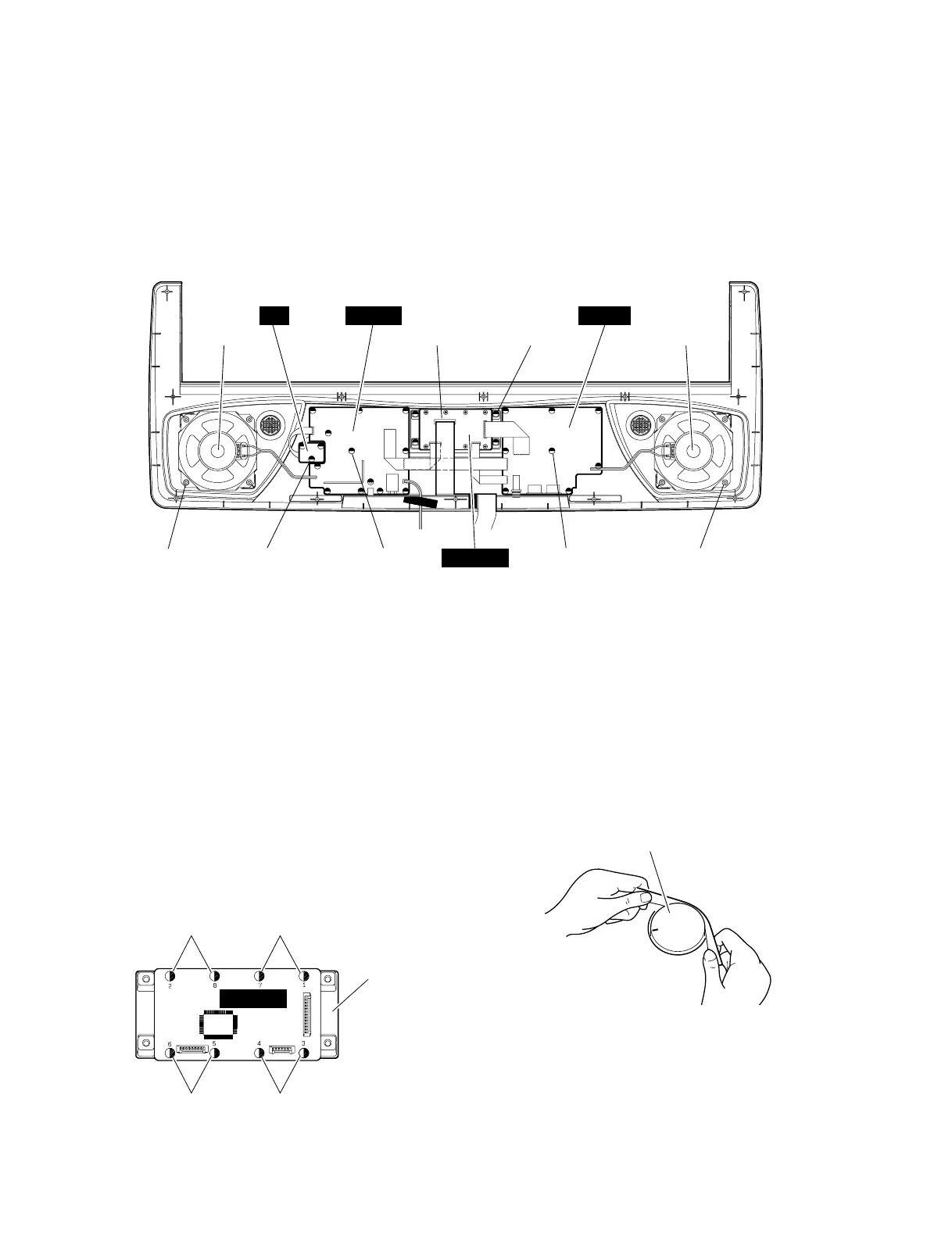
5-2. Remove the four (4) screws marked [240C].
The LCD unit can then be removed. (Fig. 4)
5-3. Remove the eight (8) screws marked [L50].
The DM-LCD circuit board can then be removed
from the LCD unit. (Fig. 5)
* When you install the DM-LCD circuit board, tighten
the screws from No.1 to No. 8 in order as shown in
Figure 5.
7. Speaker (Time required : About 8 min.)
7-1. Remove the lower case assembly.
(See procedure 1)
7-2. Remove the right and left speakers by removing
four (4) screws marked [270] from each speaker.
(Fig. 4)
3. PN-AM 1/2 Circuit Board
(Time required : About 8 min.)
3-1. Remove the lower case assembly.
(See procedure 1)
3-2. Remove the twelve (12) screws marked [240A].
The PN-AM 1/2 circuit board can then be removed.
(Fig. 4)
[240] : Bind Head Tapping Screw-B 3.0X8 MFZN2Y (EP600250)
[270] : Bind Head Tapping Screw-B 4.0X8 MFZN2Y (VP640410)
(Fig. 4)
(Fig. 6)
6. VR Circuit Board
(Time required : About 8 min.)
6-1. Remove the lower case assembly.
(See procedure 1)
6-2. Remove the volume knob from the control panel
side. (Fig. 6)
6-3. Remove the three (3) screws marked [240D]. The
VR circuit board can then be removed. (Fig. 4)
4. PN-AM 2/2 Circuit Board
(Time required : About 8 min.)
4-1. Remove the lower case assembly.
(See procedure 1)
4-2. Remove the eight (8) screws marked [240B]. The
PN-AM 2/2 circuit board can then be removed.
(Fig. 4)
Speaker (L)
[240D] x 3 [240A] x 12 [240B] x 8
[240C] x 4
[270] x 4 [270] x 4
Speaker (R)LCD Unit
DM-LCD
VR
PN-AM 1/2
PN-AM 2/2
[L50]
LCD Unit
[L50]
[L50] [L50]
DM-LCD
 Loading...