QL5/QL1
11 8
B. GAIN MIN
1 Gain (QL5: INPUT 17–32 / QL1: INPUT 9–16)
2 Distortion (QL5: INPUT 17–32 / QL1: INPUT 9–16)
3
Noise level EIN (QL5: INPUT 17–32 / QL1: INPUT 9–16)
Parameters: Short the CH IN to be measured with 150 Ω.
If the measured value is out of the above permissible
range,confi rm that “measured value – (Gain at 1kHz)
≦
-128”
is obtained.
4 Level difference (QL5:
CH17‒32/QL1:CH9‒16
)
Confirm the range of difference in the gain measured in
item 1
above as follows.
2-3. PHONES L, R
Parameters: Input from INPUT (XLR) of INPUT 1.
Assign INPUT 1 to STEREO.
Set MONITOR SOURCE to STEREO l/R.
Set PHONES LEVEL LINK to OFF.
1 Gain (PHONES L, R)
2 Distortion (PHONES L, R)
3 Residual noise (PHONES L, R)
Parameters: Turn off STEREO.
4 PHONES L to R level difference
Confirm the range of difference in the gain measured in
item 1 above as follows.
5 Maximum output (PHONES L, R)
Parameters: Assign only the built-in oscillator to STEREO and
output –27 dB from the built-in oscillator.
6 L to R crosstalk
Parameters: Set PAN fully to the L side.
Perform the same check on the R side.
3. DIGITAL IN / OUT Characteristic Inspection
3-1. DIGITAL OUT
Parameters: Use System Two.
Input from INPUT 1.
A. WORD CLOCK INT48 kHz
Parameters: Set WORD CLOCK to INT 48 kHz.
1 Gain (DIGITAL OUT)
2 f characteristic (DIGITAL OUT)
Parameters: 1 kHz is used as the reference of the permissible
range.
3 Distortion (DIGITAL OUT)
3-2. PLL Operating Range of WORD CLOCK IN
Parameters: Use the System Two.
When measuring L channel:
QL5: Use OMNI OUT 15 (L).
QL1: Use OMNI OUT 7 (L).
When measuring R channel:
QL5: Use OMNI OUT 16 (R).
QL1: Use OMNI OUT 8 (R).
Select WC IN for WORD CLOCK.
Input from INPUT 1.
Use the Dante Controller.
With the PC and Dante PRIMARY terminal of the
main unit connected with a network cable, click
the device label twice.
Click the Device Confi g tab on the Device View
screen.
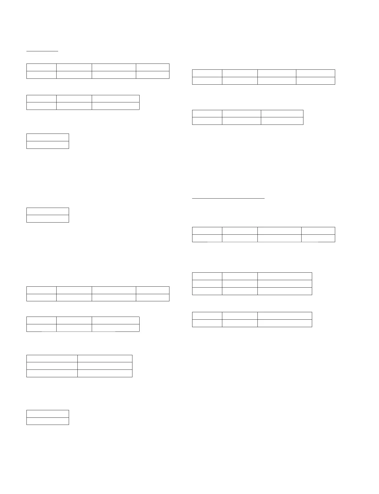
Input Frequency
Input Level
Prescribed Output Level Permissible Range
1 kHz –62 dBu +4 dBu +4±2 dBu
Input Frequency
Input Level
Prescribed Output Level Permissible Range
1 kHz 0 dBu 0 dBu 0±2 dBu
Input Frequency
Output Level Permissible Range
1 kHz +22 dBu 0.02 % or below
Input Frequency
Output Level Permissible Range
1 kHz 0 dBu 0.15 % or below
Permissible Range
Within 2 dB
Permissible Range
Within 2 dB
Permissible Range
–62 dBu or below
PHONES LEVEL Permissible Range
MAX –79 dBu or below
MIN –88 dBu or below
Input Frequency
Output Level
Permissible Range
Permissible Range(Distortion)
1 kHz +3 dBu +3±0.5 dBu 0.15 % or below
Input Frequency
Output Level (L)
Permissible Range
1 kHz +3 dBu –56 dBu or below
Input Frequency
Input Level
Prescribed Output Level Permissible Range
1 kHz +10 dBu –20 dBFS –20±2 dBFS
Input Frequency
Output Level Permissible Range
1 kHz –2 dBFS 0.002 % or below
Input Frequency
Input Level Permissible Range
20 Hz +10 dBu from –1.0 dB to +0.5 dB
20 kHz +10 dBu from –1.0 dB to +0.5 dB

 Loading...


