QL5/QL1
40
QL1 DISASSEMBLY PROCEDURE(QL1 分解手順)
Precautions
(注意事項)
Take care not to trap your fingers.
* Install the filament tape and the harness clamp in the same
way as they were before removal.
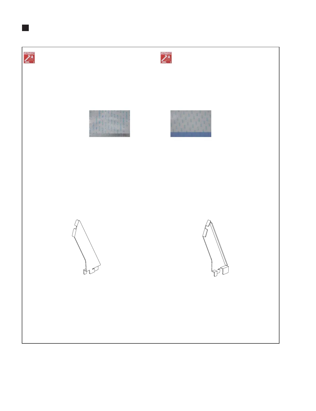
* Notes on Flat Cable
Contacts are visible from the back. Pay attention not to insert
and install the cable to the connector inversely. (Photo 1)
* MAC (Media Access Control) address are stored in the
CPUQL circuit board. If the CPUQL circuit board are
replaced, MAC address will be changed.
* After replacing the FD1S/FD1M circuit board or fader unit,
color bar and CH MAME LCD, or LCD assembly, be sure to
execute calibration of the replacement part.
* Before proceeding to procedures, prepare service stays L
and R (tools for fixing the control panels) in advance. (Fig. 1)
* IC204on CPUQLcircuit board:MRAM(Magneto
resistiveRandom AccessMemory) isa storageelement
usingmagnetism. Keepany magneticitem suchasa
screwdriveraway fromit asthe magneticforceofsuch
itemmaycausedamagetothedataofIC204andtheIC
itself.
作業中は指を挟まない様に注意してください。
※ フィラメントテープ、束線止めは、取り外す前と同じよ
うに取り付けてください。
※ フラットケーブルの注意
接点が裏面から透けて見えます。コネクタにケーブルの
表・裏を逆に差込まないように注意して取り付けてくださ
い。(写真1)
※ CPUQLシートには、MAC(Media AccessControl)アド
レスが設定されています。CPUQLシートを交換すると、
MACアドレスが変更されます。
※ FD1S/FD1Mシート又はフェーダーユニット、カラー
バーとCHNAMELCD、LCDAssyの交換後は、交換部
品のキャリブレーションを実施してください。
※ 作業を行う前に、サービスステイL、R(コントロールパ
ネル固定用工具)を用意してください。(図1)
※ CPUQLシートのIC204:MRAM(Magnetoresistive
RandomAccess Memory:磁気抵抗ランダム・アクセ
ス・メモリー)は、磁気を利用した記憶素子の為、ドラ
イバーなど磁気を帯びたものを近づけないでください。
IC204のデータやIC自身が壊れる恐れがあります。
Photo 1
(写真1)
Fig. 1
(図1)
Front Side
(表面)
Back Side
(裏面)
SERVICE STAY L
(サービスステイ L)(
WZ987700
)
SERVICE STAY R
(サービスステイ R)(
WZ987800
)

 Loading...


