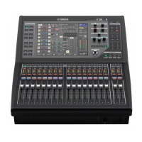
QL5/QL1
41
1. Side Pad Assembly L, R
(サイドパッドAss'yL,R)
..................................................................................................... 42
2. Control Panel S Assembly
(コンパネSAss'y)
............................................................................................................. 43
3. Lithium Battery
(リチウム電池)
.................................................................................................................................... 44
A. Disassembly Procedure of Bottom S Assembly
(ボトムSAss'yの分解)
................................................................ 44
A-1. CPUQL Circuit Board
(CPUQLシート)
........................................................................................................................ 44
A-2. FX Circuit Board
(FXシート)
........................................................................................................................................ 45
A-3. HP Circuit Board
(HPシート)
....................................................................................................................................... 46
A-4. LAMP1 Circuit Board
(LAMP1シート)
......................................................................................................................... 46
A-5. HAAD (1/2, 2/2) Circuit Boards
(HAAD(1/2,2/2)シート)
.......................................................................................... 46
A-6. DA Circuit Board
(DAシート)
....................................................................................................................................... 47
A-7. JK Circuit Board Assembly
(JKシートAss'y)
............................................................................................................. 48
A-8. Power Supply Unit
(電源ユニット)
............................................................................................................................... 48
A-9. DNT1 Circuit Board, DANTE Module 32ch
(DNT1シート、ダンテモジュール32CH)
.............................................. 48
A-10. DSP16 Circuit Board
(DSP16シート)
......................................................................................................................... 50
A-11. AC S Assembly
(ACSAss'y)
....................................................................................................................................... 50
A-12. ACSW Circuit Board, AC Inlet Assembly, PSW Connector Assembly
(ACSWシート、インレットAss'y、PSW束線)
............................................................................................................. 50
A-13. DCM Circuit Board
(DCMシート)
................................................................................................................................. 52
A-14. DC Fan Motor
(DCファンモーター)
.............................................................................................................................. 52
B. Disassembly Procedure of Control Panel S Assembly
(コンパネSAss'yの分解)
.................................................. 53
B-1. LCDC Circuit Board
(LCDCシート)
............................................................................................................................. 53
B-2. LCD Assembly
(LCDAss'y)
......................................................................................................................................... 53
B-3. PNL Circuit Board
(PNLシート)
................................................................................................................................... 54
B-4. PNR Circuit Board
(PNRシート)
.................................................................................................................................. 55
B-5. ENC Circuit Board
(ENCシート)
.................................................................................................................................. 55
B-6. USB Circuit Board
(USBシート)
.................................................................................................................................. 56
B-7. FD1M Circuit Board (CH1–16)
(FD1Mシート(CH1 〜 16))
......................................................................................... 56
B-8. FD1S Circuit Board (MASTER A, B)
(FD1Sシート(MASTERA,B))
......................................................................... 56
B-9. PN16M Circuit Board
(PN16Mシート)
......................................................................................................................... 56
B-10. PN2 Circuit Board
(PN2シート)
................................................................................................................................... 58
B-11. Crystal Display
(液晶ディスプレイ)
............................................................................................................................. 58

 Loading...