QL5/QL1
42
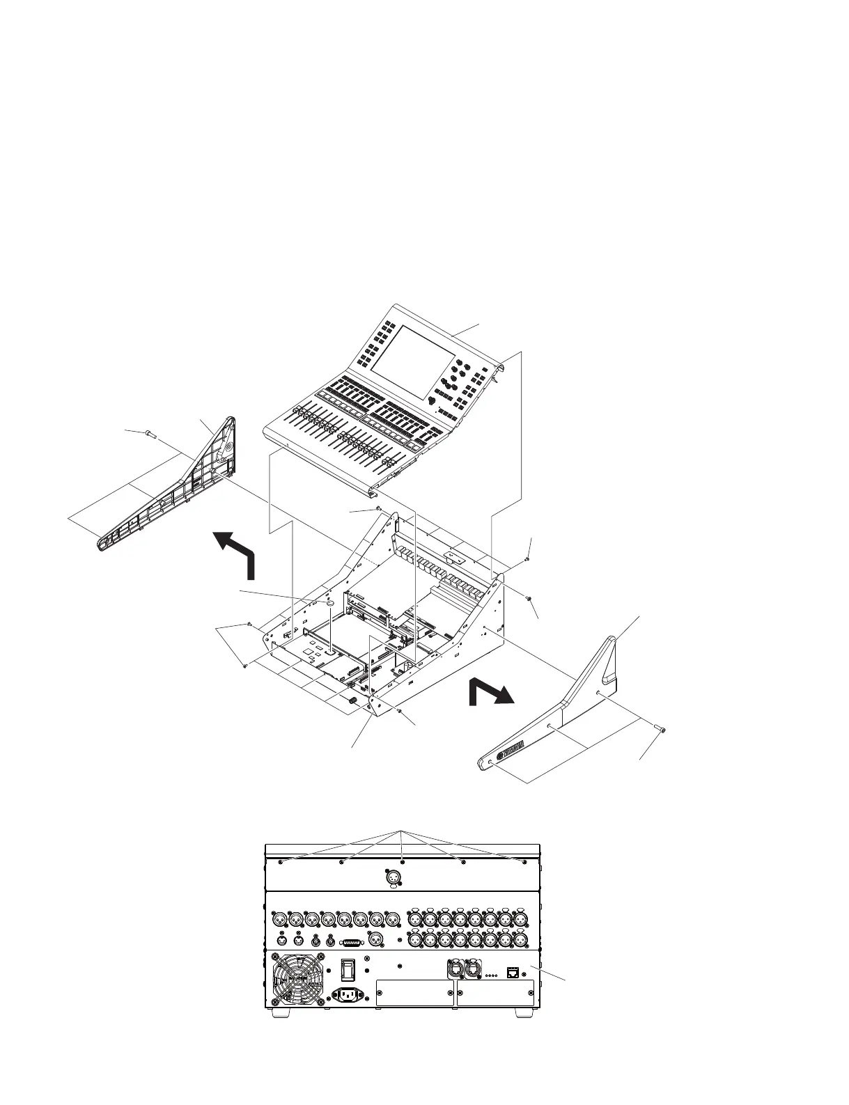
1. Side Pad Assembly L, R
(Time required: About 1 minute each)
1-1 Side Pad Assembly L:
1-1-1 Remove the three (3) machine screws marked [150].
The side pad assembly L can then be removed. (Fig. 2)
1-2 Side Pad Assembly R:
1-2-1 Remove the three (3) machine screws marked [170].
The side pad assembly R can then be removed. (Fig. 2)
* Remove the side pad assembly L, R in the direction
of the arrow in Fig. 2.
Fig. 2
(図2)
1. サイドパッドAss'yL,R
(所要時間:各約1分)
1-1 サイドパッド Ass'yL:
1-1-1 [150] の六角孔付ボルト 3 本を外して、サイドパッ
ド Ass'yL を外します。(図 2)
1-2 サイドパッド Ass'yR:
1-2-1 [170] の六角孔付ボルト 3 本を外して、サイドパッ
ド Ass'yR を外します。(図 2)
※ サイドパッド Ass'yL,R を取り外す際は、図 2 で示す
矢印の方向へ外します。
SIDE PAD ASSEMBLY L
(サイドパッド AssyL)
LITHIUM BATTERY
(リチウム電池)
SIDE PAD ASSEMBLY R
(サイドパッド
Ass’y R
)
BOTTOM S ASSEMBLY
(ボトムSAssy)
CONTROL PANEL S ASSEMBLY
(コンパネSAssy)
[150]
[170]
[120]
[130]
[130]
[120]
[120]
BOTTOM S ASSEMBLY
(ボトムSAssy)
[120]
<Rear view(裏面)>

 Loading...


