QL5/QL1
39
B-13. Crystal Display
(Time required: About 9 minutes)
B-13-1
Remove the side pad assembly L and R. (See Procedure 1)
B-13-2
Remove the control panel L assembly. (See procedure 2)
B-13-3 Remove the sheet corresponding to the location of the
subject crystal display.
• CH 1-16:
PN16S circuit board (See procedure B-10)
• CH 17-32:
PN16M circuit board (See procedure B-11)
• MASTER A, B:PN2 circuit board (See procedure B-12)
B-13-4 Remove the crystal display. (Fig. 17)
B-13-5 The crystal display and color bar lens can then be
separated. (Fig. 17)
B-13. 液晶ディスプレイ
(所要時間:約 9 分)
B-13-1 サイドパッド Ass'yL,R を外します。(1 項参照)
B-13-2 コンパネ LAss'y を外します。(2 項参照)
B-13-3 対象の液晶ディスプレイの箇所に対応するシー
トを外します。
・CH1 〜 16: PN16S シート(B-10 項参照)
・CH17 〜 32: PN16Mシート(B-11 項参照)
・MASTERA,B: PN2 シート(B-12 項参照)
B-13-4.液晶ディスプレイを外します。(図 17)
B-13-5. 液晶ディスプレイからカラーバーレンズを外し
ます。(図 17)
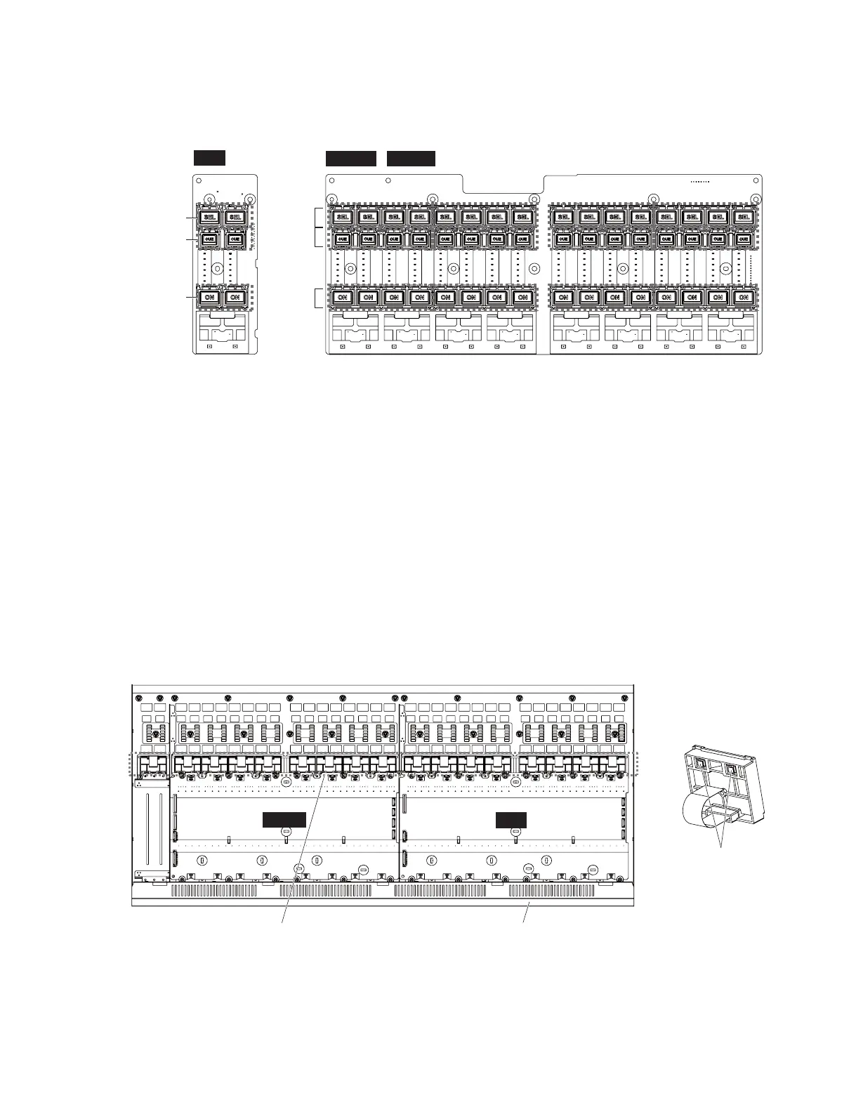
PN16M
PN16S
PN2
<Top view(上面)>
[20] x 4
[10a] x 2
[10b] x 2
[10c] x 2
[30] x 4
[40] x 4
,
Fig. 16
(図16)
Fig. 17
(図17)
COLOR BAR LENS
(カラーバーレンズ)
CRYSTAL DISPLAY
(液晶ディスプレイ)
r$3:45"-%*41-":
(液晶ディスプレイ)
CONTROL PANEL L ASSEMBLY
(コンパネLAss'y)
'%
'%.
<BottomWJew(底面)>

 Loading...


