QL5/QL1
133
DSP7 test items and display provided during execution.
1: CPU Interface (Data Bus) .................................................OK
2: CPU Interface (Chip Select) .............................................OK
3: CPU Interface (Address Bus) ............................................OK
4: E-RAM Interface (Data Bus) ............................................OK
5: E-RAM Interface (Address Bus) .......................................OK
6: SIO Connection (DSP7 → DSP6) ....................................OK
7: SIO Connection (DSP6 → DSP7) ....................................OK
8: SIO Connection (DSP7 → DSP7) ....................................OK
9: DSP7 LSI Check (DSP7 ACC) .........................................OK
The results, when judged as NG, are shown as below (for
bothDSP6 and DSP7).
1) CPU Interface/DRAM, E-RAM Interface
NG: ICxxx(1) 0000 0000 XXXX 0000 0000 0000 0000 X00X
MSB LSB
IC number DSP number x = Error bit
2) SIO Connection (DSP7 → DSP6) …
NG: 1 ICxxx(1) [Soxx] → ICxxx(1) [Sixx]
1-8. SHARC Test
Contents Checks the communication between CPU and
SHARC.
Checks SHARC SDRAM (Address Bus, Data Bus).
Checks the FLAG line between CPU and SHARC.
Example of executing screen
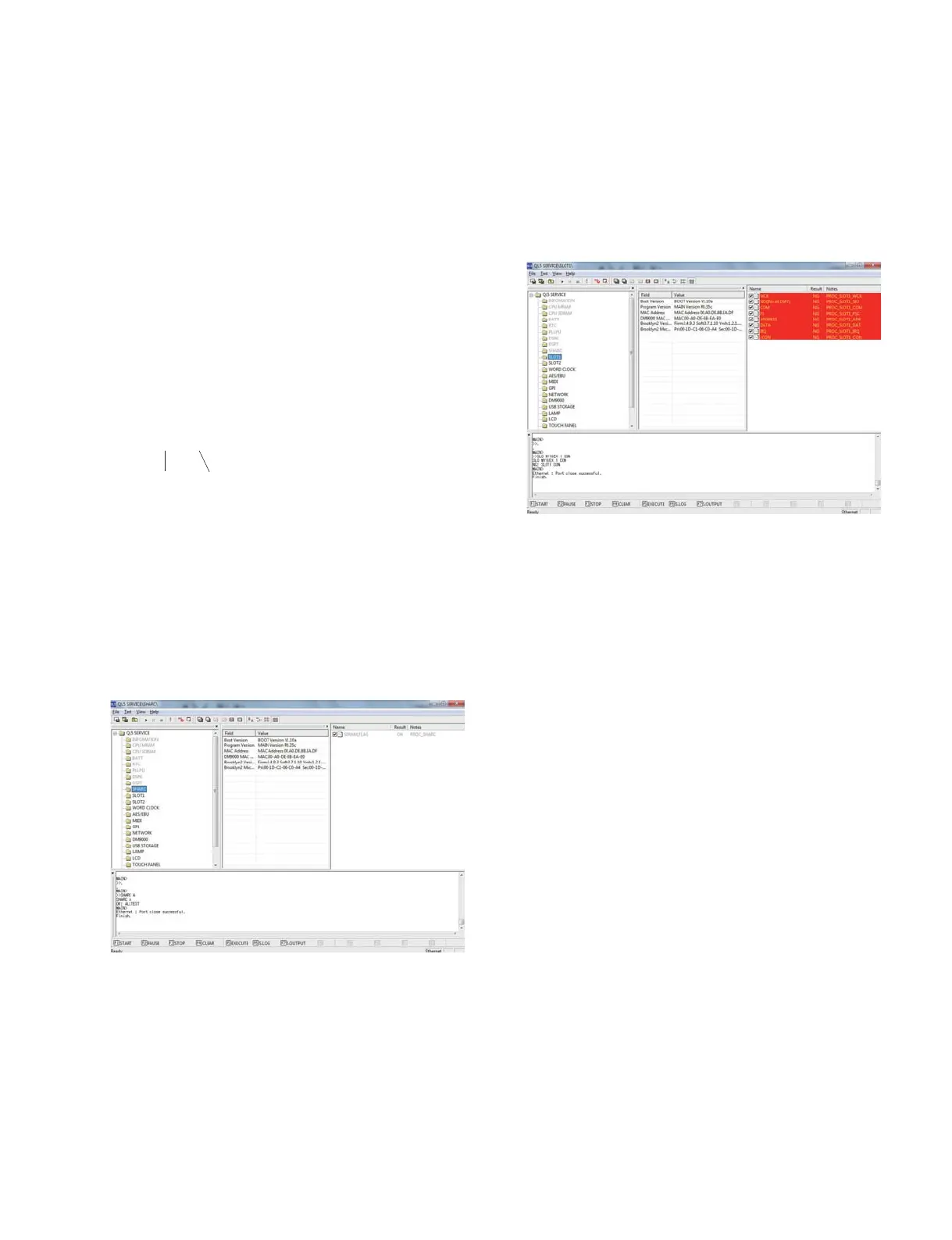
1-9. SLOT Test
Contents Checks the power voltage supplied to each interface
and SLOT of MY SLOT.
2SLOT check
Example of executing screen (In the case of SLOT1)
* The same screen appears for SLOT 2 as well but COM test is
for SLOT 1 only.
Display in case the check result is NG
WCK
NG: SLOT1 WCK MY_WC COUNT=1023
SIO
NG: [SO:12305670 → SI:00000000] SI/SO 1-0
COM
NG: SLOT1 COMM
Rx len = 0
Rx = 0x01,0x00,0x00,0x00
FS
NG: MSWCK
NG: MSSYNC
NG: FSMY
NG: SYNC
NG: 64FS & 128FS (ff)
NG: 256FS (ff)
NG: MS256 (ff)
ADDRESS
NG: SLOT1 ADDR BUS(A10..A1) XXX XXXX XXX
DATA
NG: SLOT1 DATA BUS(D15..D0) XXXX XXXX XXXX XXXX
IRQ
NG: SLOT1 IRQ
/CON
NG: SLOT1 CON
Checking SLOT power voltage
Take measurement at each terminal of MY16-EX check jig using
a tester in the Manual mode for judgment.(For measurement,
connect a cable to the connector CN102 of EX.)
The COM test is applicable to SLOT1 only.

 Loading...


