QL5/QL1
47
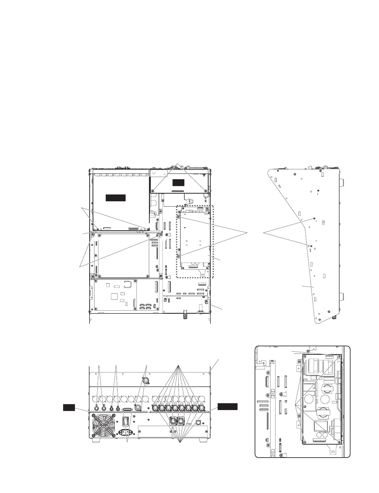
Fig. 6
(図6)
A-6. DA シート
(所要時間:約 9 分)
A-6-1 サイドパッド Ass'yL,R を外します。(1 項参照)
A-6-2 コンパネ SAss'y を固定します。(2 項参照)
A-6-3 [770] のネジ 16 本と [780] のネジ 2 本を外して、
DA シートを外します。(図 5)
※ DA シートを取り付ける際は、[770] のネジを締めてか
ら [780] のネジを締めてください。(図 5)
※ DA シートは、以下のチャンネルで使用されています。
・DA シート:OMNIOUTCH1 〜 8
A-6. DA Circuit Board
(Time required: About 9 minutes)
A-6-1
Remove the side pad assembly L and R. (See Procedure 1)
A-6-2 Fix the control panel S assembly. (See procedure 2)
A-6-3 Remove the sixteen (16) screws marked [770] and
two (2) screws marked [780]. The DA circuit board
can then be removed. (Fig. 5)
* When installing the DA circuit board, first tighten
the screw marked [770] and then tighten the screws
marked [780]. (Fig. 5)
* The circuit board from DA are used for the following
channels:
· DA circuit board: OMNI OUT CH 1 – 8
[630A]
[630B]
[480B]
[360]
BOTTOM S ASSEMBLY
(ボトムSAssy)
BOTTOM S ASSEMBLY
(ボトムSAssy)
BOTTOM S ASSEMBLY
(ボトムSAssy)
POWER ANGLE TOP
(パワーアングルトップ)
HAAD ANGLE
(HAAD アングル)
[600]
[600]
HAAD
(2/2)
HAAD
(2/2)
JK
JK
<Rear view(裏面)>
<Top view(上面)> <Right side view(右側面)>
[480A][490] [490]
q
w
e
r
LOCK NUT
(ロックナット)
A
C
D
B
A
A: POWER SUPPLY UNIT
(電源ユニット)
[340]
EARTH FILM
(アースフィルム)
 Loading...


