QL5/QL1
58
B-10. PN2 シート
(所要時間:約 7 分)
B-10-1 サイドパッド Ass'yL,R を外します。(1 項参照)
B-10-2 コンパネ SAss'y を外します。(2 項参照)
B-10-3 FD1S シートを外します。(B-8 項参照)
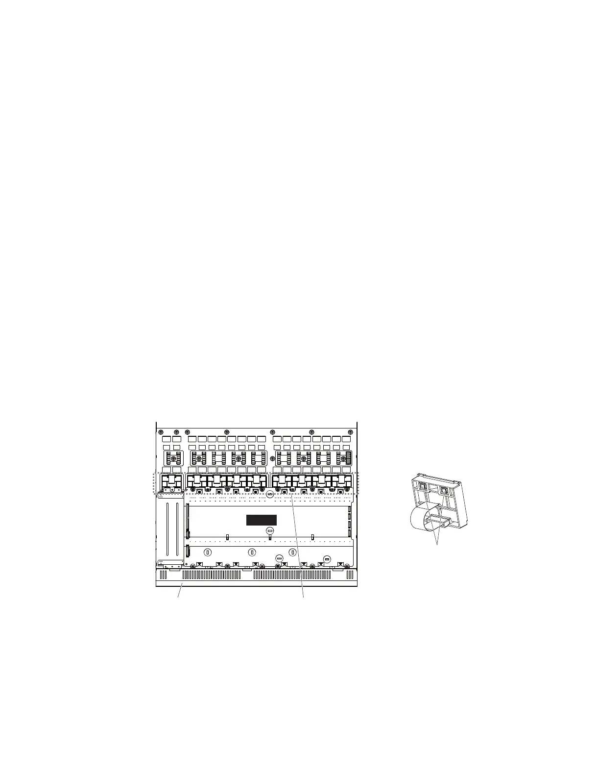
B-10-4 [130] のネジ 1 本を外して、PNPUSH 金具 2 を
外します。(図 14)
B-10-5 [80] のネジ 3 本を外して、PN2 シートを外します。
(図 14)
※ PN2 シートには、下記のボタンがついています。
(図 15)
・[10a]:ボタン(大)(SEL) 2 個
・[10b]:ボタン(小)(CUE) 2 個
・[10c]:ボタン(大)(ON) 2 個
B-11. 液晶ディスプレイ
(所要時間:約 8 分)
B-11-1 サイドパッド Ass'yL,R を外します。(1 項参照)
B-11-2 コンパネ SAss'y を外します。(2 項参照)
B-11-3 対象の液晶ディスプレイの箇所に対応するシー
トを外します。
・CH1 〜 16: PN16M シート(B-9 項参照)
・MASTERA,B: PN2 シート(B-10 項参照)
B-11-4.液晶ディスプレイを外します。(図 16)
B-11-5. 液晶ディスプレイからカラーバーレンズを外し
ます。(図 16)
B-10. PN2 Circuit Board
(Time required: About 7 minutes)
B-10-1
Remove the side pad assembly L and R. (See Procedure 1)
B-10-2
Remove the control panel S assembly. (See procedure 2)
B-10-3
Remove the
FD1S circuit board
. (See procedure B-8)
B-10-4 Remove the screw marked [130]. The PN push angle
2 can then be removed. (Fig. 14)
B-10-5 Remove the three (3) screws marked [80]. The PN2
circuit board can then be removed. (Fig. 14)
* The PN2 circuit board contains the following
buttons (Fig. 15)
· [10a]: Button L (LARGE) (SEL) 2 pc.
· [10b]: Button S (SMALL) (CUE) 2 pc.
· [10c]: Button L (LARGE) (ON) 2 pc.
B-11. Crystal Display
(Time required: About 8 minutes)
B-11-1
Remove the side pad assembly L and R. (See Procedure 1)
B-11-2
Remove the control panel S assembly. (See procedure 2)
B-11-3
Remove the sheet corresponding to the location of the
subject crystal display.
• CH 1-16:PN16M circuit board (See procedure B-9)
• MASTER A, B:PN2 circuit board (See procedure B-10)
B-11-4 Remove the crystal display. (Fig. 16)
B-11-5 The crystal display and color bar lens can then be
separated. (Fig. 16)
COLOR BAR LENS
(カラーバーレンズ)
CRYSTAL DISPLAY
(液晶ディスプレイ)
r$3:45"-%*41-":
(液晶ディスプレイ)
CONTROL PANEL S ASSEMBLY
(コンパネSAss'y)
'%.
<3FBSWJew(裏面)>
Fig. 16
(図16)

 Loading...


