ALTERNATOR
TNV IDI Service Manual
11-13
Alternator
3. Position the stator assembly (Figure 11-13, (1))
on the front frame housing studs.
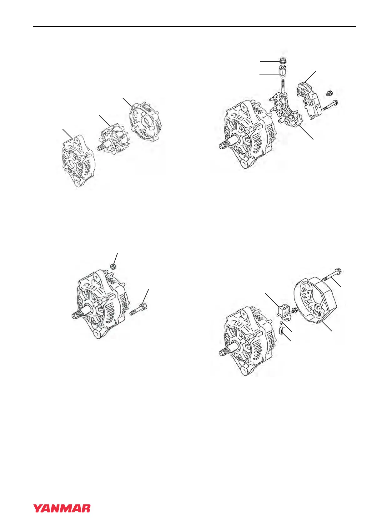
4. Lubricate the shaft of the rotor assembly
(Figure 11-14, (1)). Press the rotor assembly
into the front frame housing (Figure 11-14, (2))
and rear frame housing (Figure 11-14, (3)).
Figure 11-14
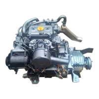
5. Align the front frame housing with the rear
frame housing. Reinstall the two bolts
(Figure 11-15, (1)) and two nuts
(Figure 11-15, (2)).
Figure 11-15
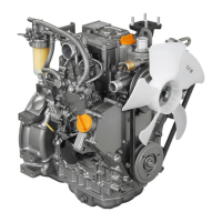
6. Reinstall the insulation bushing
(Figure 11-16, (4)) and nut (Figure 11-16, (3)).
Figure 11-16
7. Reassemble the regulator assembly
(Figure 11-16, (1)) to the holder
(Figure 11-16, (2)).
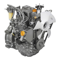
8. Reinstall the brush holder (Figure 11-17, (3)),
springs (Figure 11-17, (4)) and brushes
(Figure 11-17, (5)).
9. Reattach the regulator assembly and holder to
the rear frame housing.
Figure 11-17
10. Reinstall the rear cover (Figure 11-17, (2)) to
the rear frame housing with three bolts
(Figure 11-17, (1)).
100266A
2
1
3
TNV_IDI_ServiceManual_A4.book 13 ページ 2012年2月24日 金曜日 午前10時24分



 To Next Page