COOLING SYSTEM
TNV IDI Service Manual
8-7
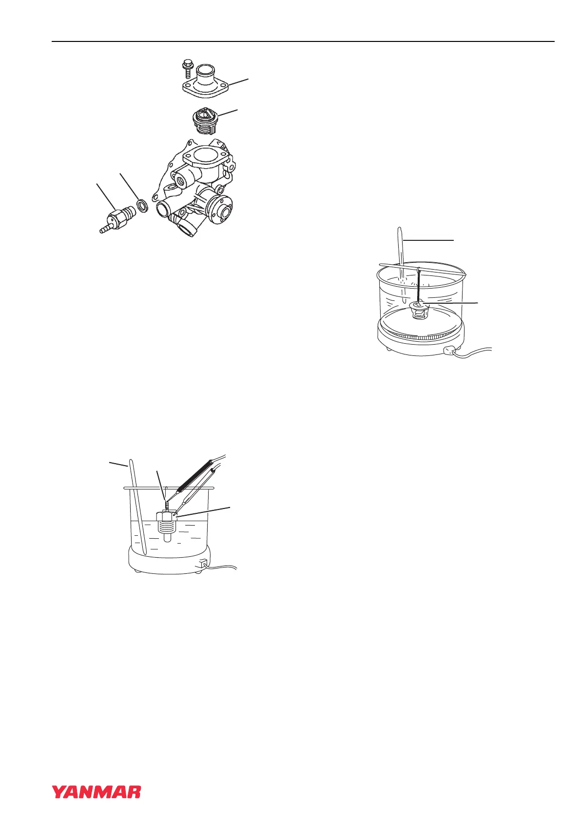
Engine Coolant Pump
Figure 8-5
8. Remove the thermostat (Figure 8-5, (2)).
Remove the temperature switch
(Figure 8-5, (3)) and gasket (Figure 8-5, (4)).
Discard the gasket.
Cleaning and Inspection
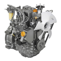
Temperature Switch
1. Check for proper operation of the temperature
switch. Connect a continuity light or ohmmeter
to the temperature switch. Connect one lead to
the terminal of the switch (Figure 8-6, (1)) and
the other lead to the metal portion of the switch
(Figure 8-6, (2)).
Figure 8-6
2. Place the temperature switch and an accurate
thermometer (Figure 8-6, (3)) in engine
coolant.
3. Slowly increase temperature of the fluid using
an external heat source.
4. The temperature switch is normal if the
continuity light or ohmmeter indicates continuity
when the fluid temperature reaches
225°F - 235°F (107°C - 113°C).
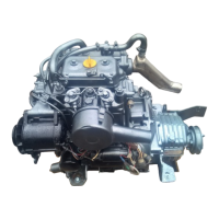
Thermostat
1. Check for proper operation of the thermostat.
Place the thermostat (Figure 8-7, (1)) and an
accurate thermometer (Figure 8-7, (2)) in warm
water.
Figure 8-7
2. Slowly increase temperature of the water using
an external heat source.
3. The thermostat is normal if it starts to open at
the temperature value stamped on the flange of
the thermostat, and fully opens as the
temperature of the water is increased.
Radiator Cap
1. Check for proper operation of the radiator cap.
Install the radiator cap (Figure 8-8, (1)) on a
cooling system tester.
TNV_IDI_ServiceManual_A4.book 7 ページ 2012年2月24日 金曜日 午前10時24分