FUEL SYSTEM
7-8
TNV IDI Service Manual
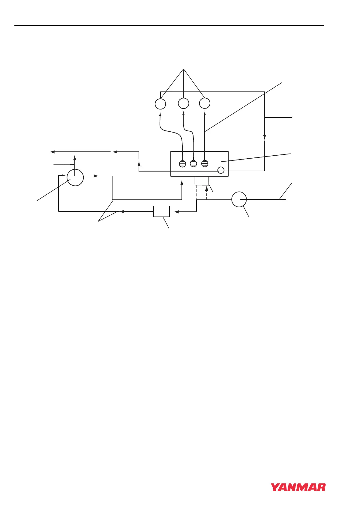
Fuel System Diagram
FUEL SYSTEM DIAGRAM
1 –Diesel Fuel Supply
2 –Fuel Filter / Water Separator
3 –Mechanical Fuel Pump (Used in place of the
electric fuel pump on some models)
4 –Electric Fuel Pump (Used on models
without mechanical fuel pump)
5 –Low-Pressure Fuel Supply Lines
6 –Fuel Filter
7 –Fuel Injection Pump
8 –High-Pressure Fuel Injection Lines
9 –Fuel Injectors
10– Fuel Return from Fuel Injectors
11 – Air Bleed Orifice
12 –Fuel Return to Tank
Figure 7-2
(1)
(9)
(7)
(12)
(6)
(11)
(5)
(4)
(2)
(3)
(8)
(10)
0001058A
TNV_IDI_ServiceManual_A4.book 8 ページ 2012年2月24日 金曜日 午前10時24分
 Loading...