2. Product explanation
(1)
Controls
and
Equipment
Controls
and
Equipment
Mechanism
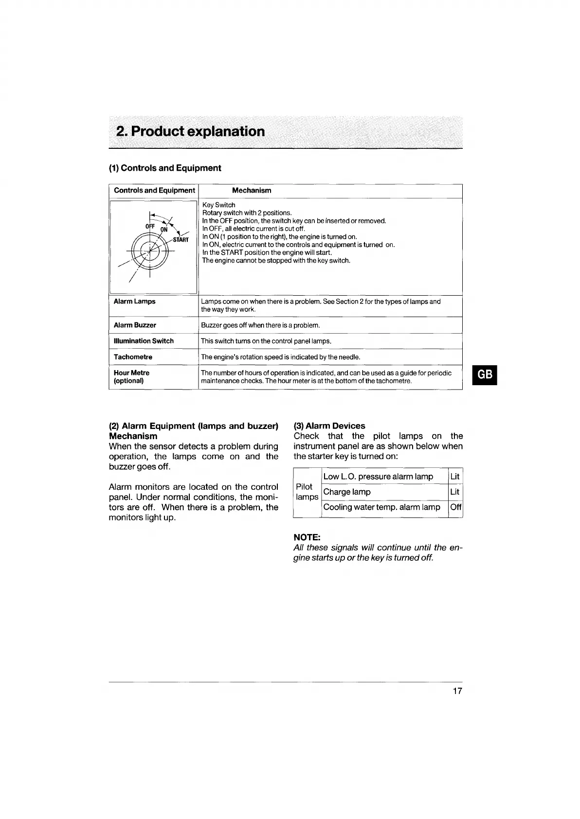
Key Switch
o~
Rotary switch with 2 positions.
In
the OFF position, the switch key can
be
inserted or removed.
In
OFF, all electric current is cut off.
~M~
In
ON
(1
position to the right), the engine is tumed on.
In
ON, electric current to the controls and equipment is turned on.
In
the
START position
the
engine will start.
./'
.
The engine cannot be stopped with the key switch .
/
Alarm
Lamps
Lamps come on when there is a problem. See Section 2 for the types
of
lamps and
the way they work.
Alarm
Buzzer
Buzzer goes off when there is a problem.
Illumination
Switch
This switch turns on the control panel lamps.
Tachometre
The engine's rotation speed is indicated by the needle.
Hour
Metre
The number
of
hours
of
operation is indicated, and can be used as a guide for periodic
(optional)
maintenance checks. The hour meter is at the bottom
of
the tachometre.
(2)
Alarm
Equipment
(lamps
and
buzzer)
Mechanism
When the sensor detects a problem during
operation, the
lamps come on and the
buzzer goes off.
Alarm monitors are located on the control
panel.
Under normal conditions, the moni-
tors are off. When there is a
problem, the
monitors
light up.
(3)
Alarm
Devices
Check that the pilot lamps on the
instrument
panel are as shown below when
the starter key is turned on:
Low
L.O.
pressure alarm lamp Lit
Pilot
Charge lamp Lit
lamps
Cooling
water temp. alarm lamp Off
NOTE:
All
these signals will continue until the en-
gine starts
up
or
the key is turned off.
17