6. Piping diagram
(See
appendix
A at the back of
this
book)
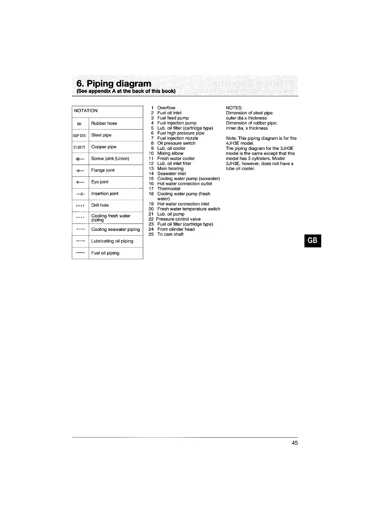
NOTATION
RH
Rubber hose
SGP
STS
Steel pipe
C1201T
Copper pipe
-t\t-
Screw joint (Union)
-II-
Flange joint
+-
Eye
joint
-<-
Insertion joint
~
-
--
Drill hole
--
--
C.0<?ling
fresh water
pIping
----
Cooling seawater piping
---
Lubricating oil piping
--
Fuel
oil piping
1
Overflow
2 Fuel oil inlet
3 Fuel feed pump
4
Fuel injection pump
5 Lub.
oil filter (cartridge type)
6
Fuel high pressure pipe
7
Fuel injection nozzle
8 Oil pressure switch
9 Lub.
oil cooler
10
Mixing elbow
11
Fresh water cooler
12
Lub. oil inlet filter
13 Main bearing
14 Seawater
inlet
15 Cooling water pump (seawater)
16 Hot water connection outlet
17 Thermostat
18
Cooling water pump (fresh
water)
19 Hot water connection
inlet
20
Fresh water temperature switch
21
Lub. oil pump
22
Pressure control valve
23 Fuel oil filter (cartridge type)
24 From
cilinder head
25 To cam shaft
NOTES:
Dimension of steel pipe:
outer dia.x thickness
Dimension of rubber pipe:
inner dia. x thickness
Note: This piping diagram is for the
4JH3E
model.
The piping diagram for the 3JH3E
model is the same except that this
model has 3 cylinders. Model
3JH3E, however, does not have a
lube oil cooler.
45