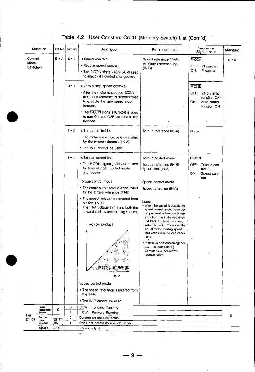
Table 4.2 User Constant Cn-01 (Memory Switch) List (Cont'd)
No.I Setting Description Reference Input
Selection
Bit
Sequence
Signal Input Standard
Control B • A 0 • 0 <Speed control> Speed reference (IN-A) P-CON 0 • 0
Mode Auxiliary reference input
Selection • Regular speed control. (IN-B) i OFF: PI control.
• The P-CON signal (1CN-24) is used ON: P control
to effect P/PI control changeover.
0 • 1 <Zero clamp speed control> P-CON
• After the motor is stopped (ZCLVL). OFF: Zero clamp
the speed reference is disconnected function OFF
to execute Ihe zero speed stop ON: Zero clamp
function, function ON
• The P-CON signal (1CN-24) is used
to turn ON and OFF the zero clamp
function.
I • 0 <Torque controlI> Torque reference0N-A) None
• The motor output torque is controlled
by the torque reference (IN-A).
• The IN-B cannot be used.
1 • 1 <Torque control I1> Torque control mode P-CON
• The P-CON signal (1CN-24) is used Torque reference 0N-B) OFF: Torque con-
for torque/speed control mode Speed limil (IN-A) trol
changeover. ON: Speed con-
trol
Torque control mode Speed control mode
• The motor output torque is controlled Speed reference (IN-A)
by the torque reference (IN-B).
• The speed limit can be entered from
Outside (IN-A). Noles:
• When the speed isoutsidethe
The IN-A voltage (+) limits both the speedcOntrolrange,Ihetorque
torward and reverse running speeds, proportionaltothe speeddiffer-
encefrom the limitis negatively
fed back to place the speed
] MOTOR SPEED I withinthe limit. Therefore,the
actualmotorrotating speed
' _ limitvarieswi_hthe load COndi-
t!ons.
:_'__'?_'_f • In case otcontinuous regener-
ation (tension COntrol).
: Contactyour YASKAWA
O representative.
IN'A
Speed control mode
• The speed reference is entered from
the IN-A.
• The IN-El cannot be used.
Pc,me 0, CCW: Forward Running
I:lo=_nhlcde 0
Seem= I CW: Forward Running
For Enc_ef 1 0 Detects an enceder error. O
On-02 E,r. [_"YIDete_m 1 Does not detect an encoder error•
Spare 2 to F Do not adjust.
 Loading...