6.2 Servomotor Main Circuit Cables
6.2.2 Servomotor Main Circuit Cables for Servomotors with Holding Brakes
6-10
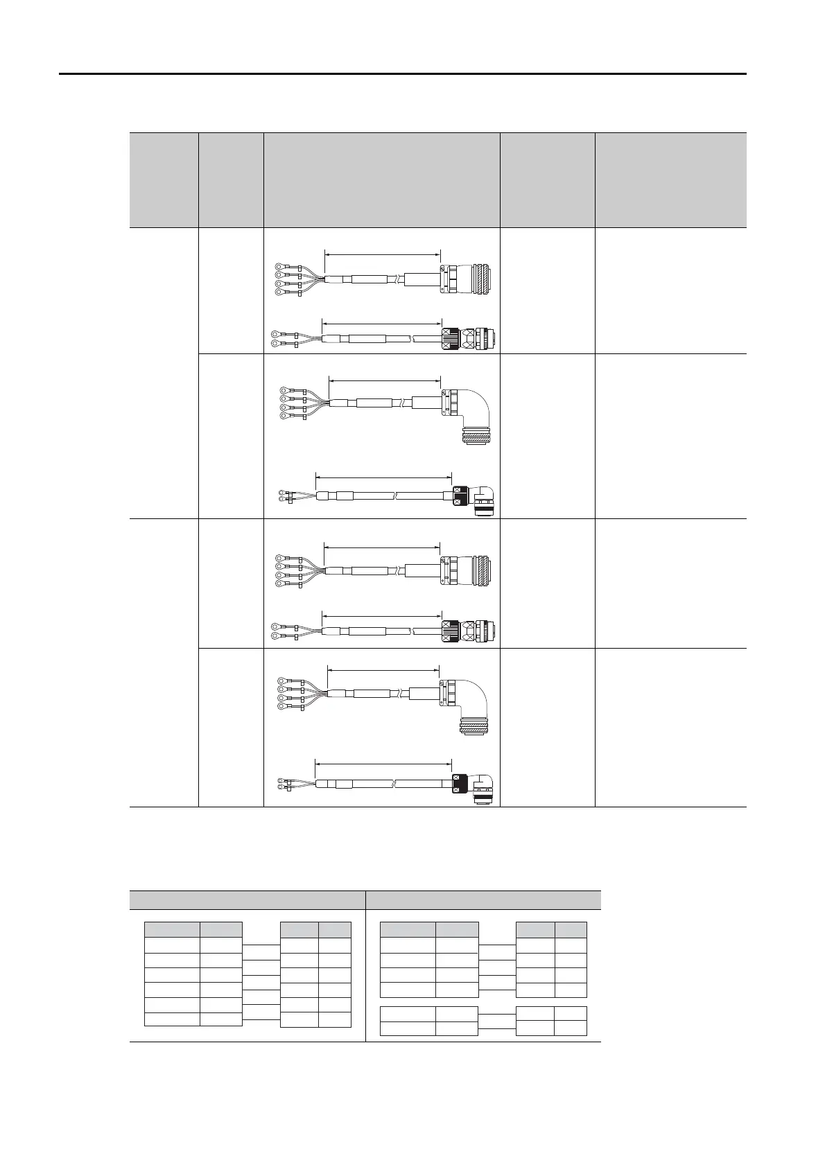
Wiring Specifications
Note: There is no polarity for the connection to the brake.
SGM7G-
55 or
-75
5.5 kW or
7.5 kW
Straight
Standard
Cable:
JZSP-
UVAA31-
-E
Flexible Cable:
JZSP-
UVAA41-
-E
• Main Circuit Power
Supply Cable
Standard Cable:
JZSP-UVAA01-
-E
Flexible Cable:
JZSP-UVAA21-
-E
• Holding Brake Cable
*2
JZSP-U7B23--E
Right-
angle
*1
Standard
Cable:
JZSP-
UVAA32-
-E
Flexible Cable:
JZSP-
UVAA42-
-E
• Main Circuit Power
Supply Cable
Standard Cable:
JZSP-UVAA02-
-E
Flexible Cable:
JZSP-UVAA22-
-E
• Holding Brake Cable
*2
JZSP-U7B24--E
SGM7G-
1A or
-1E
11 kW or
15 kW
Straight
Standard
Cable:
JZSP-
UVAB31-
-
E
Flexible Cable:
JZSP-
UVAB41-
-
E
• Main Circuit Power
Supply Cable
Standard Cable:
JZSP-UVAB01-
-E
Flexible Cable:
JZSP-UVAB21-
-E
• Holding Brake Cable
*2
JZSP-U7B23--E
Right-
angle
*1
Standard
Cable:
JZSP-
UVAB32-
-
E
Flexible Cable:
JZSP-
UVAB42-
-
E
• Main Circuit Power
Supply Cable
Standard Cable:
JZSP-UVAB02-
-E
Flexible Cable:
JZSP-UVAB22-
-E
• Holding Brake Cable
*2
JZSP-U7B24--E
*1. The lead installation direction is away from the load.
*2. Flexible Cables are provided as a standard feature.
For 300 W or 450 W For 850 W to 15 kW
Continued from previous page.
Servomo-
tor Model
Connec-
tor Type
External Dimensions
Order Num-
bers of Main
Power Supply
Cable and
Holding Brake
Cable
Individual Cable Order
Numbers
L
Brake end
Motor end
L
SERVOPACK end Motor end
PinSignal
SignalWire Color
PE
5
4
3
2
1
Servomotor Connector
Phase U
Brake
Brake
FG
Phase V
Phase W
Phase V
Phase W
Phase U
Brake
Brake
FG
Red
Black
Black
Green/yellow
White
Blue
SERVOPACK Leads
PinSignal
SignalWire Color
A
B
C
D
Servomotor Connector
FG
Phase W
Phase V
Phase U
FG
Phase W
Phase V
Phase U
Green/yellow
Blue
White
Red
SERVOPACK Leads
1
2
Brake
Brake
Brake
Brake
Black
White
 Loading...


