12.2 Magnetic Contactors
12-7
12
SERVOPACK Peripheral Devices
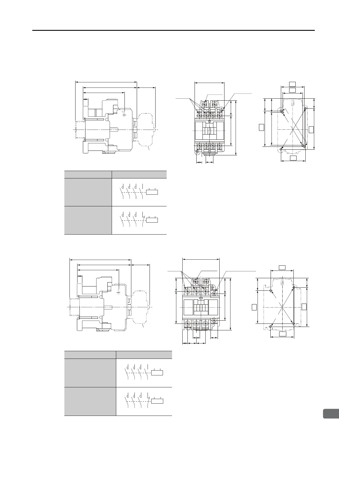
External Dimensions
Model: SC-03
Model: SC-4-1
• You can use any of the following three mounting methods.
: 34 × (48 to) 52
: 30 × 48
: 35 × 60
• Mounting screws: 2 × M4
Use two mounting holes in diagonally opposing corners to
mount the Magnetic Contactor.
Unit: mm
Approx. mass: 0.32 kg
• You can use either of the following two mount-
ing methods.
: 34 × (48 to) 52
: 35 × 60
• Mounting screws: 2 × M4
Use two mounting holes in diagonally opposing
corners to mount the Magnetic Contactor.
Unit: mm
Approx. mass: 0.36 kg
14.5
(20.5)
18.5
52
35
60
30
34
23
81
43
43
10
7.7
(28)
80
61
8.5
90 (for a rail height of 15)
Mounting Hole
Dimensional Diagram
With auxiliary contact
block mounted
(Mounting at 48 mm is also possible.)
Main terminals
Coil terminal
M3.5
Auxiliary terminal
M3.5
M3.5
Auxiliary Contacts Contact Structure
1NO
1NC
1/L1 3/L2 5/L3
13
A1
A2
2/T1 4/T2 6/T3
14
1/L1 3/L2 5/L3
21
2/T1 4/T2 6/T3
22
A1
A2
14.5
18.5
(20.5)
52
35
60
34
(28)
81
61
8.5
23
81
43
53
9.7
7.7
13
13
8
49
20
Mounting Hole
Dimensional Diagram
(Mounting at 48 mm is also possible.)
Main terminals
M4
Coil terminal
M3.5
Auxiliary terminal
M3.5
91 (for a rail height of 15)
With auxiliary
contact block
mounted
Auxiliary Contacts Contact Structure
1NO
1NC
1/L1 3/L2 5/L3
13
A1
A2
2/T1 4/T2 6/T3
14
1/L1 3/L2 5/L3
21
2/T1 4/T2 6/T3
22
A1
A2
 Loading...


