12.2 Magnetic Contactors
12-8
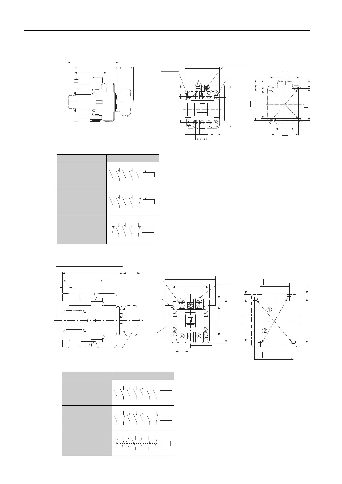
Model: SC-5-1
Model: SC-N1 or SC-N2
• You can use either of the following two mount-
ing methods.
: 54 × (56 to) 60
: 50 × 60
• Mounting screws: 2 × M4
Use two mounting holes in diagonally opposing
corners to mount the Magnetic Contactor.
Unit: mm
Approx. mass: 0.38 kg
• You can use either of the following two mount-
ing methods.
: 70 × 75
: (55 to) 65 × 90
• Mounting screws: 2 × M4
Use two mounting holes in diagonally opposing
corners to mount the Magnetic Contactor.
Unit: mm
Approx. mass: 0.59 kg
(28)
81
61
8.5
20
49
2343
81
14.5
14.5
60
(16.5)
60
7.7
9.7
13
13
64
54
(35)
50
With auxiliary
contact block
mounted
Mounting Hole
Dimensional Diagram
Auxiliary terminal
M3.5
Coil terminal
M3.5
Auxiliary terminal
M3.5
Main
terminals M4
91 (for a rail height of 15)
(Mounting at 56 mm is also possible.)
Auxiliary Contacts Contact Structure
2NO
1NO/1NC
2NC
A1 A2
13 1/L1 3/L2 5/L3
23
14 2/T1 4/T2 6/T3
24
A1 A2
13 1/L1 3/L2 5/L3
21
14 2/T1 4/T2 6/T3
22
A1 A2
11
1/L1 3/L2 5/L3
21
12
2/T1 4/T2 6/T3
22
With auxiliary
contact block
mounted
96
106 (for a rail height of 15)
65.5
10.5
(28)
Main
terminals
M5
Coil
terminal
M3.5
Auxiliary
terminal
M3.5
(99)*
74
12.4
16.5
87
59.5 14.3
*
:
With two side-on auxiliary contact blocks mounted.
*
45 (50 max.)
Mounting Hole
Dimensional Diagram
6.5
75
9
70
65 (60 min.)
Auxiliary Contacts Contact Structure
4NO
2NO/2NC
4NC
A1 A2
13
14 22 2/T1 4/T2 6/T3 44 32
21 1/L1 3/L2 5/L3 43 31
A1 A2
13
14 22 2/T1 4/T2 6/T3 44 32
21 1/L1 3/L2 5/L3 43 31
A1 A2
13
14 22 2/T1 4/T2 6/T3 44 32
21 1/L1 3/L2 5/L3 43 31
 Loading...


