Programming 102
Fig. 71 Frequency Bias 2 Applied to Analog frequency reference
Function: Motor Temperature
Setting: E
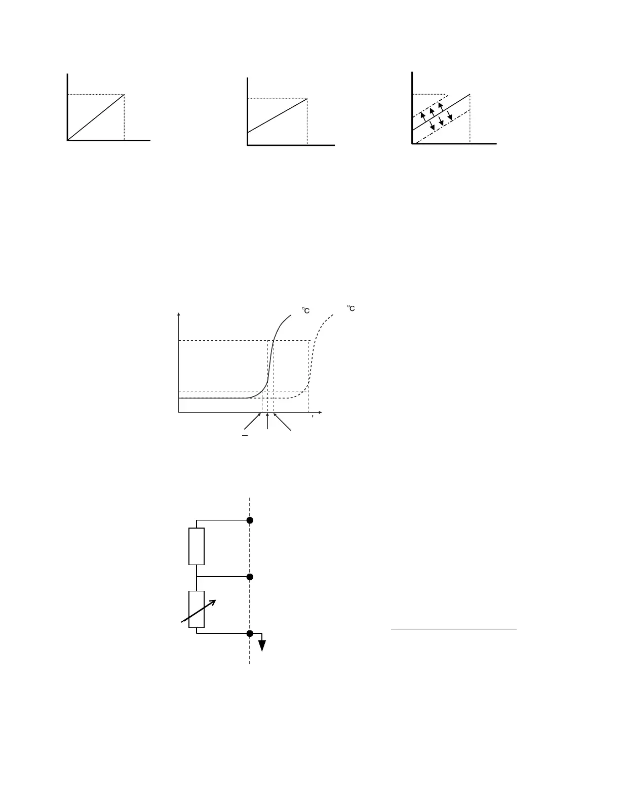
In addition to or in place of the OL1 (Motor Overload) fault of the Drive, it is possible to use a PTC (Positive Temperature
Coefficient) thermistor for motor insulation protection. The PTC thermistors are built into the windings of some motors and
will vary their resistance based on temperature. An example PTC characteristic is show below.
Fig. 72 PTC Thermistor Temperature-Resistance Value Characteristics
Connection of the thermistor to the Drive is shown below, in addition make sure Dip Switch S1-2 is in the OFF position, see Figure 55.
Fig. 73 Thermistor To Drive Connection Diagram
Factory Default
10V
A1 Voltage
Speed
A1 Voltage
10V
H3-03
H3-02
With H3-03 applied
Speed
A1 Voltage
10V
With both H3-03 and analog input bias
(H3-09=0) applied
H3-02
H3-03
Speed
Command
pee
Command
Speed
Command
(H3-09=D) applied
Tr: Temperature threshold value
Tr
Tr+5TrTr 5
550
1330
Resistance (ohms)
Class F
150
Class H
180
Temperature
+V
(+15 V, 20 mA)
2
(0-10 Vdc)
C
PTC Thermistor
Branch resistance
18 k
Ω
*1
*1 The resistance value of 18 k
Ω
is only valid for
using a 3-phase PTC with the characteristics shown in
the figure below.
above.
(R
ptc@Tr
x3) x (V
S
-V
ptc@OH3
)
V
ptc@OH3
Rbranch =
 Loading...


