Programming 111
H4-07 Terminal FM Signal Level Selection
H4-08 Terminal AM Signal Level Selection
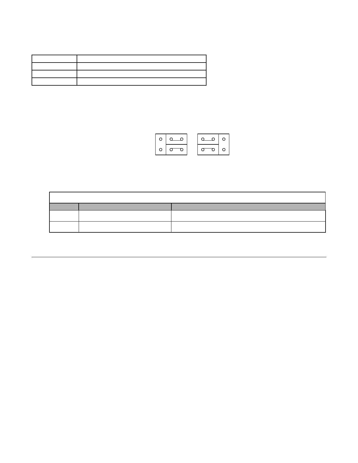
Parameters H4-07 and H4-08 determine whether analog outputs are configured as 0 to 10Vdc, -10 to +10Vdc, or 4-20mA. The
jumper position of CN15 on the removable terminal board must correspond to the parameter setting for the proper voltage or
current level output.
Fig. 80 Jumper CN15
H5 Serial Communication Setup
This section explains the parameters associated with Modbus Serial Communication. Serial communication can be performed with
Programmable Logic Controllers (PLCs) or similar devices using the Modbus protocol. Modbus communication is configured
using 1 master (PLC) and a maximum of 31 slaves. Serial communication between master and slave is normally initiated by the
master and responded to by the slaves.The master performs serial communication with one slave at a time. Consequently, the slave
address of each slave must be initially set, so that the master can perform serial communication using that address. Slaves receiving
commands from the master perform the specified functions, and send a response back to the master.
See F7 Drive Users Manual TM.F7.01 Appendix D for further details on setting up Modbus Communication.
H5-01 Drive Node Address
Setting Range: 0 to 20 hex
Factory Default: 1F hex
In order for a master to be able to communicate with the Drive using serial communications, the Drive must have a unique
node address. The Drive is given a node address if H5-01≠0. The node addresses do not have to be assigned in sequential order
but they must be unique, i.e. no two Drives on the same serial network can be assigned the same address. After setting the
Drive address with the H5-01 parameter, the power to the Drive must be cycled for the addressing to take effect.
Leaving H5-01= 0 will disable responses to MEMOBUS communications.
Setting Description
0 0 to 10 Vdc (factory default)
1 -10 to +10 Vdc
2 4 - 20 mA
Table 22 Jumper CN15
Name Multi-function Analog Output Output Range
CH1 FM V: 0 to 10V or -10V to +10V (default) I: 4 to 20mA
CH2 AM V: 0 to 10V or -10V to +10V (default) I: 4 to 20mA
CH1
CH2
CN15
VI
 Loading...


