Programming 40
The Drive can be programmed to utilize digital inputs to change between four presets speeds and a jog speed. It is a two-step
process to set the Drive up for preset speeds. First, d1-01 through d1-04 and d1-17 must be programmed with the desired
preset speeds and the desired jog speed, respectively. Next, up to three of the Drive’s digital inputs (Terminals S3 through S8)
need to be programmed (via parameters H1-01 to H1-06) and wired (to normally open contacts) as Multi-step Speed Reference 1,
Multi-step Speed Reference 2, and Jog Frequency.
As shown in the above table, it is possible to use analog inputs in place of Frequency Reference 1 and Frequency
Reference 2.
If b1-01= “1: Terminals” then the analog input A1 will be used instead of Frequency Reference 1 for the first preset speed.
If b1-01= “0: Operator”, then Frequency Reference 1 will be used.
If H3-09= “2: Aux Reference” then the analog input A2 will be used instead of Frequency Reference 2 for the second
preset speed. If H3-09≠2 then Frequency Reference 2 will be used.
d2 Reference Limits
d2-01 Frequency Reference Upper Limit
Setting Range: 0.0 to 110.0%
Factory Default: 100.0%
d2-02 Frequency Reference Lower Limit
Setting Range: 0.0 to 110.0%
Factory Default: 0.0%
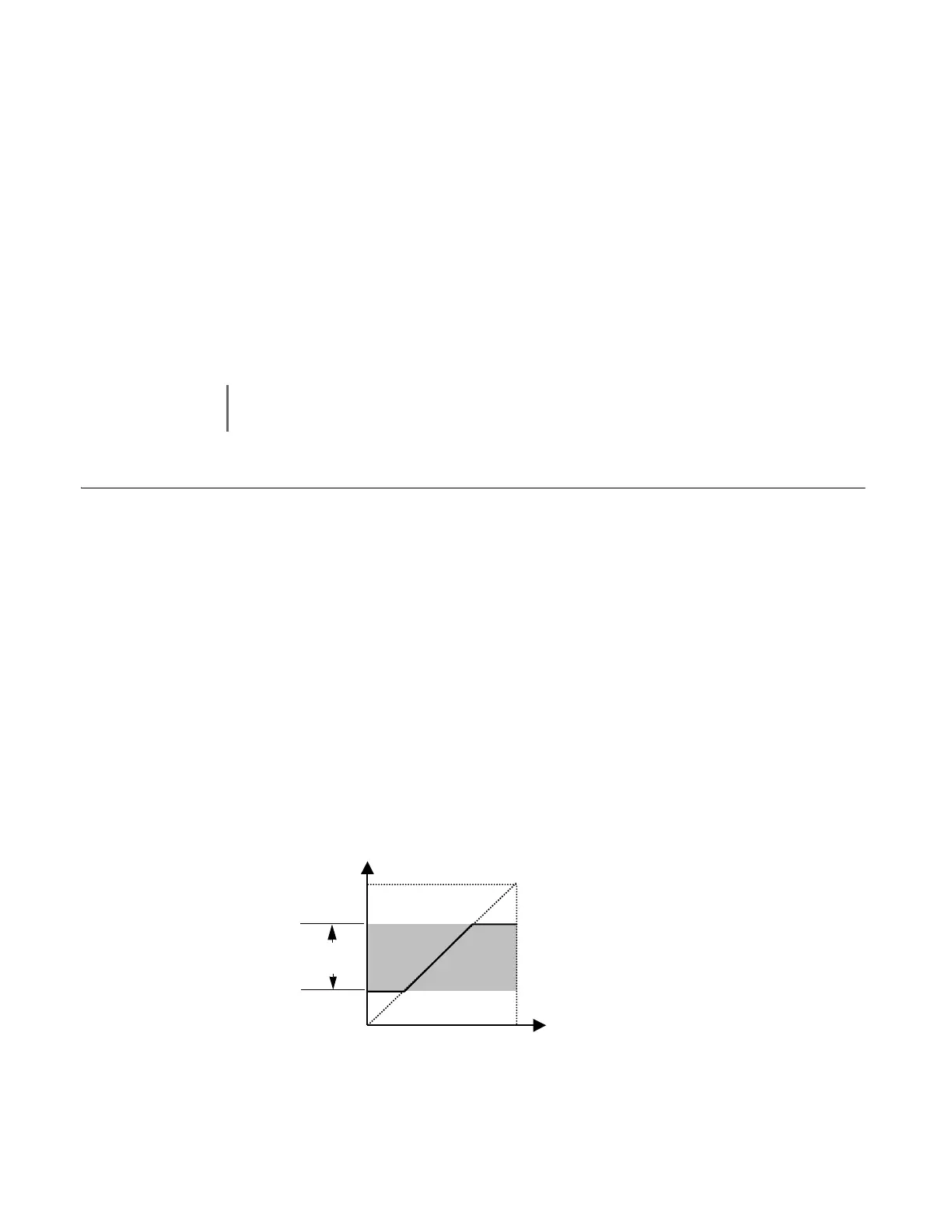
The use of parameters d2-01 and d2-02 places limitations on the frequency reference that the Drive will accept. The parameters
are set in units of percentage of the maximum frequency (E1-04) and cause dead bands on any remote frequency reference input.
By entering upper or lower frequency limits, the Drive programmer can prevent operation of the Drive above or below levels that
may cause resonance and or equipment damage.
Fig. 32 Frequency Reference Upper and Lower Limit Effects on the frequency reference
IMPORTANT
The programming of d1-01 through d1-04 and d1-17 will be affected by the setting of o1-03. The programming
of these parameters will be in the units specified by Display Scaling parameter (o1-03).
-
-
Fre
uenc
Reference U
er Limit
Fre
uenc
Reference Lower Limit
Internal S
eed Command
Set S
eed Command
d2-01
d2-02
Operating
Range