Programming 132
is done with several strategically mounted thermistors. If any of the heatsink thermistors measure a temperature in excess of
the setting of L8-02, the Drive will fault (OH2) and either ramp to stop using the active deceleration rate (L8-03= “0: Ramp to
Stop”), coast to stop (L8-03= “1: Coast to Stop”), ramp to stop using the C1-09 fast stop deceleration rate (L8-03= “2: Fast-
Stop”), alarm (OH) and continue running (L8-03 = “3: Alarm Only”), alarm (OH) and continue running but at a reduced speed
(L8-03= “4: Alarm & Reduce”). If the digital output is configured for OH Prealarm (H2-01= “20: OH PreAlarm”), it will close
whenever the heatsink temperature is greater than the L8-02 level no matter what the setting is of L8-03.
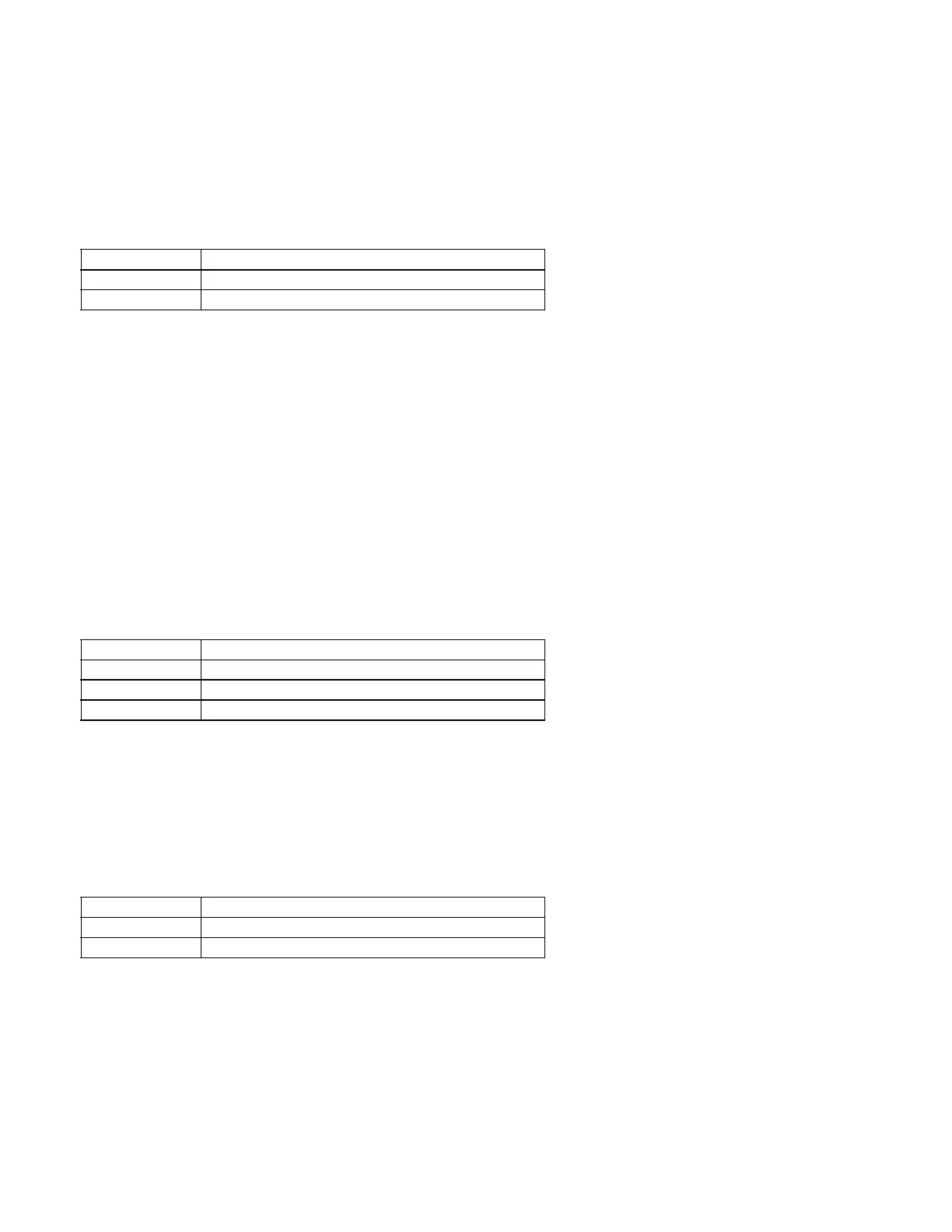
L8-05 Input Phase Loss Protection
The input phase loss detection circuit monitors the DC bus current ripple and activates when the one of the input phases are lost.
The detection circuit calculates the maximum and minimum values of the DC bus voltage in one second intervals, and compares
the difference (ΔV) between these values with an internal detection level. If ΔV reaches or exceeds the detection level, then after
0.5 second, input phase loss is detected; a PF fault occurs, and the motor coasts to stop.
Input phase loss detection is disabled in the following cases:
· A Stop command is input.
· Magnetic Contactor (MC) shuts OFF.
· CPU A/D converter fault (CPF5).
· During deceleration.
· Output current ≤ 30% of Inverter rated current.
L8-07 Output Phase Loss Protection
The output phase loss detection circuit monitors the DCCT and activates when one or more of the output phases are lost. The
detection circuit calculates the RMS current value (I
RMS
) for each of the phases and compares it with an internal output
detection level. If I
RMS
decreases to or below the detection level for 10 seconds, an output phase loss (LF) fault occurs, and the
motor coasts to stop.
L8-09 Output Ground Fault Detection Selection
The Drive has a ground fault detection circuit that activates when the current to ground exceeds 50% of the Drive’s rated output
current. The current to ground is determined by comparing the measured current on each of the output phases. If the current to
ground is determined to be above 50% of the Drive’s rated output current the digital operator will display a GF and the Drive will
coast to stop.
Setting Description
0Disabled
1 Enabled (factory default)
Setting Description
0Disabled
1 1-Phase Loss Detection
1 2/3-Phase Loss Detection (factory default)
Setting Description
0Disabled
1 Enabled (factory default)

 Loading...


