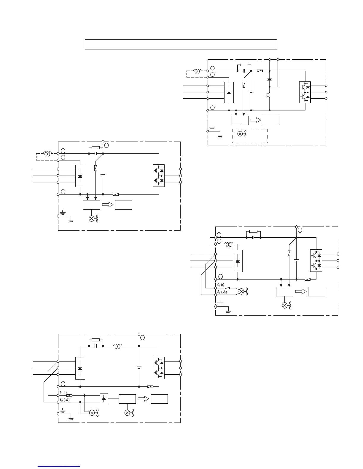
Main Circuit Configuration Block Diagrams 230V
CIMR-G5M20P41F to 27P51F
GPD515C-A003 to -A033
CIMR-G5M20111F to 20151F
GPD515C-A049 to -A064
CIMR-G5M20181F, 20221F
GPD515C-A080, -A096
CIMR-G5M20300F to 20750F
GPD515C-A130 to -A300
1-8
+ 1
+ 2
_
L1 (R)
L2 (S)
L3 (T)
+
Power
Supply
Control
Circuit
Cooling Fan
(RCC)
U (T1)
V (T2)
W (T3)
(DCL
Option)
+ 3
_
L1 (R)
L2 (S)
L3 (T)
+
Power
Supply
Control
Circuit
Internal
Cooling Fan
(RCC)
U (T1)
V (T2)
W (T3)
+ 3
Cooling Fan
+ 2
+ 1
_
L1 (R)
L2 (S)
L3 (T)
+
Power
Supply
Control
Circuit
Internal
Cooling Fan
(RCC)
U (T1)
V (T2)
W (T3)
+ 3
Cooling Fan
When using DC input as main circuit
power, connect 230Vac to control power
transformer terminals l (r) and l (s).
When using DC input as main circuit
power, connect 230Vac to control power
transformer terminals l (r) and l (s).