1-9
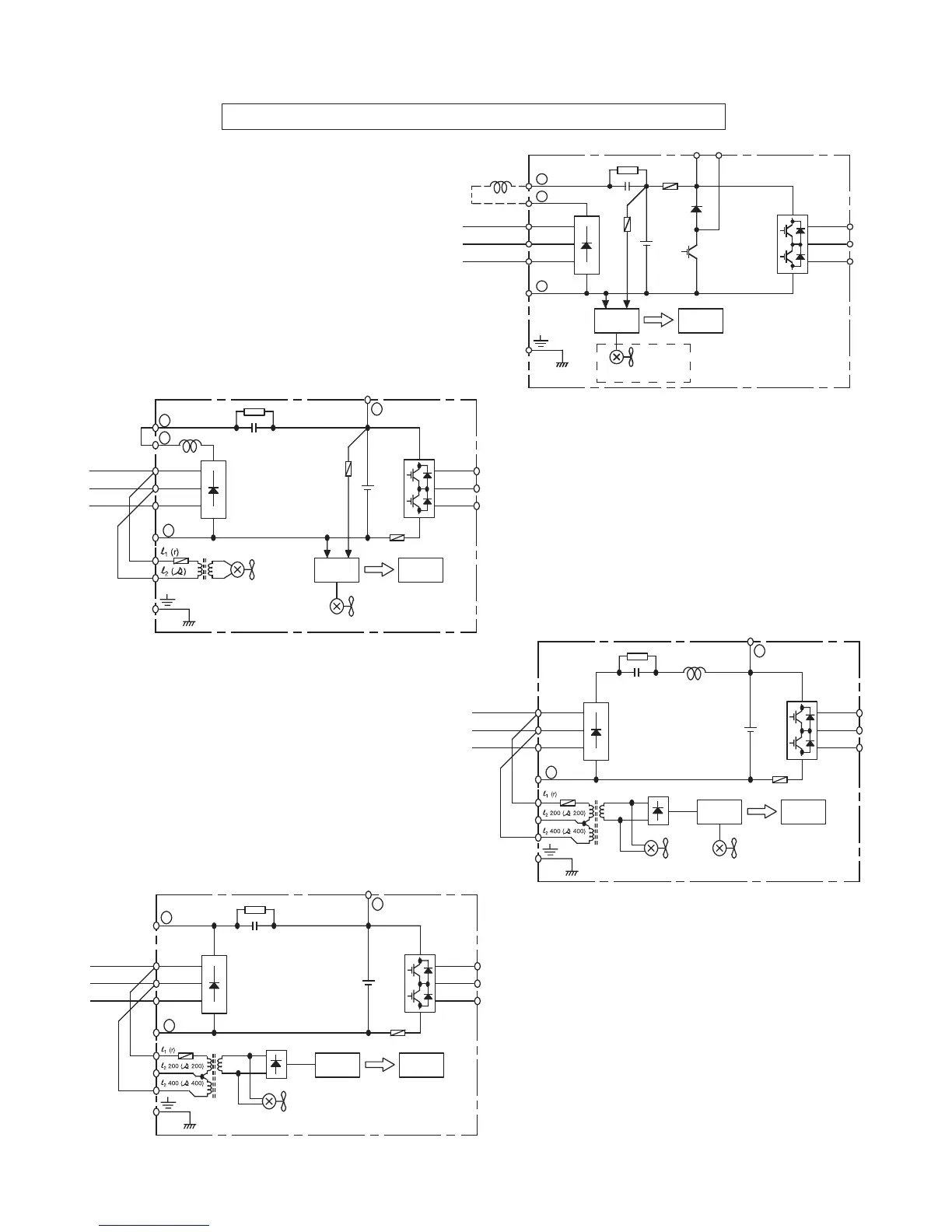
Main Circuit Configuration Block Diagrams 460V
CIMR-G5M40P41F to 40151F
GPD515C- B001 to - B034
CIMR-G5M40181F to 40451F
GPD515C- B041 to - B096
CIMR-G5M40551F to 41600F
GPD515C- B128 to - B302
CIMR-G5M41850F to 43000F
GPD515C- B340 to - B605
_
L1 (R)
L2 (S)
L3 (T)
+
Power
Supply
Control
Circuit
Internal
Cooling Fan
(RCC)
U (T1)
V (T2)
W (T3)
+ 3
Cooling Fan
+ 2
+ 1
_
L1 (R)
L2 (S)
L3 (T)
+
Power
Supply
Control
Circuit
Internal
Cooling Fan
(RCC)
U (T1)
V (T2)
W (T3)
+ 3
Cooling Fan
_
L1 (R)
L2 (S)
L3 (T)
+
Power
Supply
Control
Circuit
(RCC)
U (T1)
V (T2)
W (T3)
+ 3
Cooling Fan
+ 1
When using DC input as main circuit
power, connect 460Vac to control power
transformer terminals l
1
(r) and l
2
(s).
When using DC input as main circuit
power, connect 460Vac to control
power transformer terminals l
1
(r) and
l
2
400 (s400).
When using DC input as main
circuit power, connect 460Vac to
control power transformer
terminals l
1
(r) and l
2
400 (s400).