All basic interconnections (using the Digital Operator) are shown in Figures 1-3 and 1-4.
1 . 4 . 1 M a i n C i r c u i t I n p u t / O u t p u t
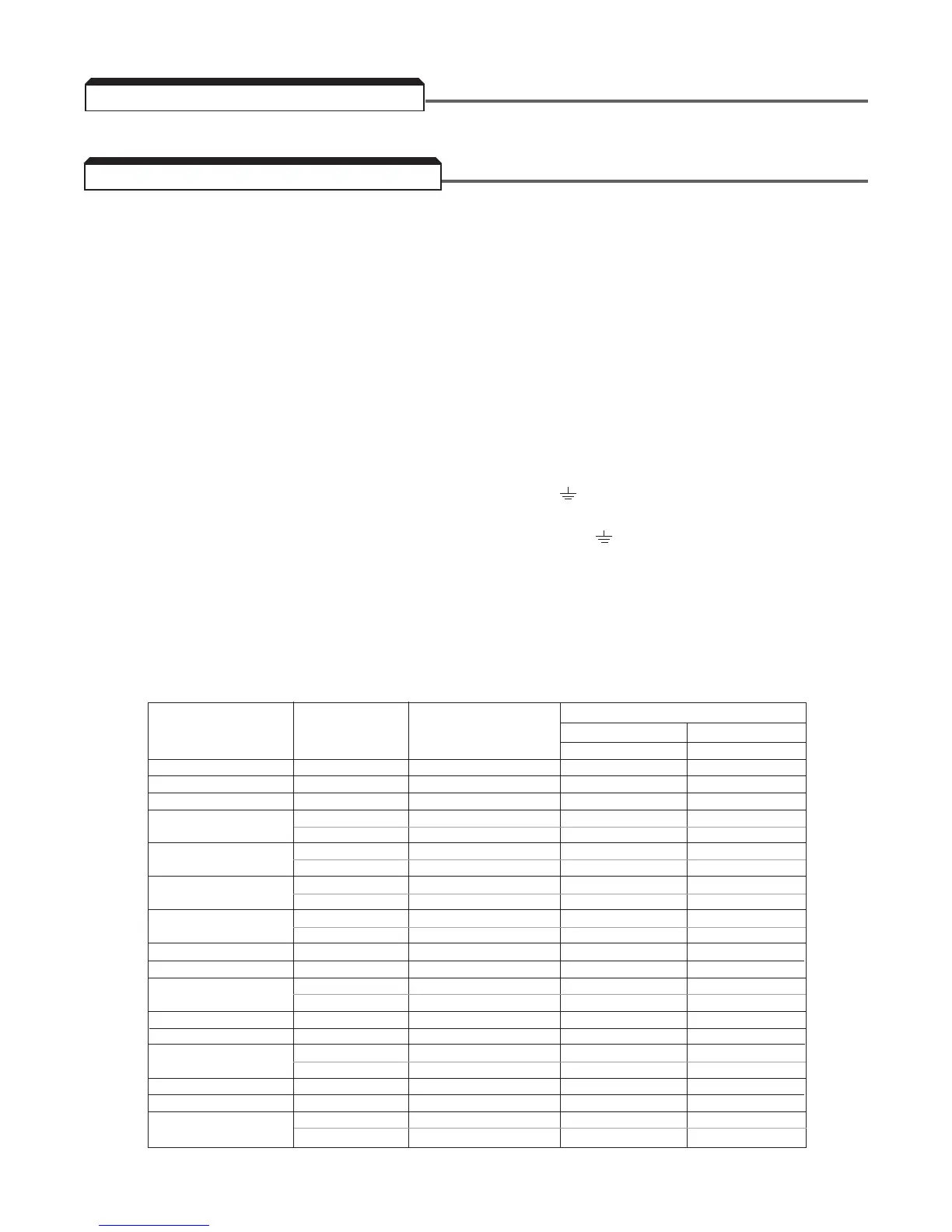
Complete wire interconnections according to Table 1-2, Figure 1-3 and Figure 1-4. Be sure to
observe the following:
• Use 600V vinyl-sheathed wire or equivalent. Wire size and type should be determined by local
electrical codes.
• Avoid routing power wiring near equipment sensitive to electrical noise.
• Avoid running input and output wiring in the same conduit.
• NEVER connect AC main power to output terminals T1(U), T2(V), and T3(W).
• NEVER allow wire leads to contact metal surfaces. Short-circuit may result.
• NEVER connect power factor correction capacitors to the drive output. Consult
Yaskawa when connecting noise filters to the drive output.
• WIRE SIZING MUST BE SUITABLE FOR CLASS I CIRCUITS.
• When connecting motor to drive’s output terminals, include a separate ground wire. Attach ground
wire solidly to motor frame and to drive’s ground terminal.
• When using armored or shielded cable for connection between drive and motor, solidly connect
armor or shield to motor frame, and to drive’s ground terminal.
• Motor lead length should NOT EXCEED 164 feet (50 meters), and motor wiring should be run in
a separate conduit from other power wiring. If lead length must exceed this distance, reduce
carrier frequency (see paragraph 5.8) and consult factory for proper installation procedures.
• Use UL listed closed loop connectors or CSA certified ring connectors sized for the selected wire
gauge. Install connectors using the correct crimp tool recommended by the connector
manufacturer.
1-2
1.4 ELECTRICAL INSTALLATION
WIRE SIZE
TERMINAL CLOSED-LOOP
CLAMPING TORQUE
AWG mm
2 SCREW CONNECTOR
STEEL COPPER
lb-in N-m lb-in N-m
20 0.5 M3.5 1.25 - 3.5 7.8 0.9 7.0 0.8
18 0.75 M4 1.25 - 4 13.0 1.5 10.4 1.2
16 1.25 M4 1.25 - 4 13.0 1.5 10.4 1.2
M4 2 - 4 13.0 1.5 10.4 1.2
14 2
M5 2 - 5 26.1 20.9 3.1 2.4
M4 3.5 - 4 13.0 1.5 10.4 1.2
12 3.5
M5 3.5 - 5 26.1 20.9 3.1 2.4
M4 5.5 - 4 13.0 1.5 10.4 1.2
10 5.5
M5 5.5 - 5 26.1 20.9 3.1 2.4
M5 8 - 5 26.1 20.9 3.1 2.4
8 8
M6 8 - 6 40.9 34.8 4.8 4.1
6 14 M6 14 - 6 40.9 34.8 4.8 4.1
4 22 M8 22 - 8 100.0 82.6 11.7 10.7
M8 38 - 8 100.0 82.6 11.7 10.7
2 38
M10 38 - 10 182.6 156.5 21.4 18.4
1/0 60 M10 60 - 10 182.6 156.5 21.4 18.4
3/0 80 M10 80 - 10 182.6 156.5 21.4 18.4
M10 100 - 10 182.6 156.5 21.4 18.4
4/0 100
M12 100 - 12 313.0 191.3 36.7 23.1
MCM300 150 M12 150 - 12 313.0 191.3 36.7 23.1
MCM400 200 M12 200 - 12 313.0 191.3 36.7 23.1
M12 325 - 12 313.0 191.3 36.7 23.1
MCM650 325
M16 325 - 16 313.0 191.3 36.7 23.1