1 . 4 . 4 C o n tr o l C i r c u i t
All basic control circuit (signal) interconnections are shown in the appropriate diagram:
• Interconnections for external two-wire control in combination with the Digital Operator are
shown in Figure 1-3.
• Interconnections for external three-wire control in combination with the Digital Operator
are shown in Figure 1-4.
Make wire connections according to Figures 1-3, 1-4 and Table 1-3; observe the following:
• Signal Leads: Terminals 1-8 & 11; 12-17 & 33; and 21-27.
• Control Leads: Terminals 9 & 10 and 18-20.
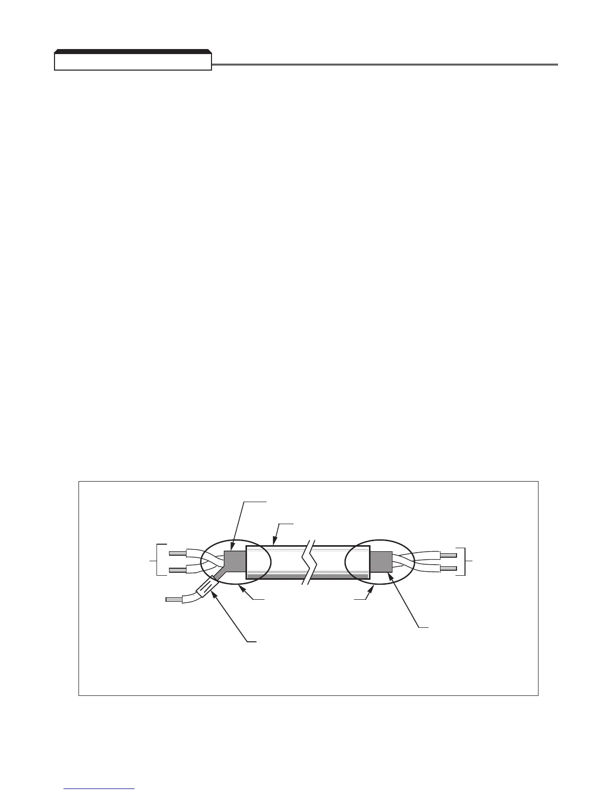
• Use twisted shielded or twisted-pair shielded wire (20-16 AWG [0.5 – 1.25mm2]) for
control and signal circuit leads. The shield sheath MUST be connected at the drive end
ONLY (terminal 12). The other end should be dressed neatly and left unconnected
(floating). See Figure 1-2B.
• Signal leads and feedback leads (PG) must be separated from control leads
main circuit leads and any other power cables to prevent erroneous operation caused
by electrical noise.
• Lead length should NOT EXCEED 164 feet (50 meters). Wire sizes should be determined
considering the voltage drop.
• All AC relays, contactors and solenoids should have RC surge supressors installed across
their coils.
• All DC relays, contactors and solenoids should have diodes installed across their coils.
1-15
TO GPD 515
SIGNAL
TERMINALS
TO SHIELD
SHEATH
TERMINAL
(TERM. 12)
WRAP BOTH ENDS
OF SHEATH WITH
INSULATING TAPE
Figure 1-2B. Shielded Sheath Termination