126 YASKAWA TM.iQp.02 iQpump Drive Programming Manual
■
P1-09 High Feedback Level
Setting Range: 0.0 to 6000.0
Factory Default: 155.0 (system units P1-02)
The iQpump drive can be configured to display a High Feedback (HFB) alarm when the feedback level rises above the programmed High
Feedback Level (P1-09). The “HFB” alarm will turn off when the feedback level falls below P1-09 plus the Hysteresis Level (P1-13).
Setting P1-09 to a value of 0 will disable this function. This function is active during operation in the Hand Mode, Auto Mode, Pre-
Charge, and Thrust-Bearing Mode.
The High Feedback Level (P1-09) works in conjunction with High Level Fault Time (P1-10). The units for this parameter are determined
by the System Units (P1-02).
■ P1-10 High Level Fault Delay Time
Setting Range: 0 to 3600 sec
Factory Default: 2 sec
The iQpump drive can be configured to display a High Feedback (HFB) alarm when the feedback level rises above the programmed High
Feedback Level (P1-09) for the time programmed in the High Level Fault Delay Time (P1-10).
Setting P1-10 to a value of 0 will disable this function.
The High Level Fault Delay Time (P1-10) works in conjunction with High Feedback Level (P1-09).
Note: This function is active during operation in the Hand Mode, Auto Mode, Pre-Charge, and Thrust-Bearing Mode.
■ P1-11 Maximum Setpoint Difference <0032>
Setting Range: 0.0 to 6000.0
Factory Default: 0.0 (system units P1-02)
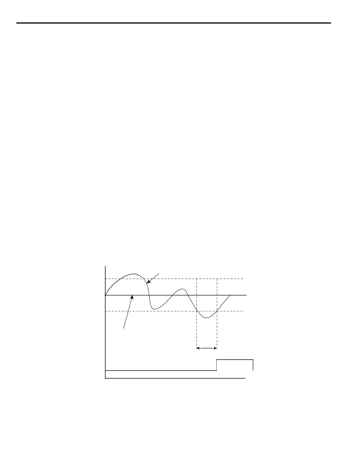
The iQpump drive can be configured to display a Not Maintaining Setpoint (NMS) fault when the difference between the setpoint and the
feedback exceeds the Maximum Setpoint Difference (P1-11). When the Maximum Setpoint Difference has been exceeded, the drive will
trip on NMS fault and will coast to a stop when the fault occurs.
Setting P1-11 to a value of 0 will disable this function. This function is only active during operation in the Auto Mode.
The Maximum Setpoint Difference (P1-11) works in conjunction with the Not Maintaining Setpoint (P1-12). The units for this parameter
are determined by the System Units (P1-02).
Figure 1. 97
Figure 102 Not Maintaining Setpoint (NMS) Fault
TIME
Not Maintaining
Setpoint (NMS) Fault
Not Maintaining
Setpoint Time P1-12
P1-11
P1-11
SETPOINT
PRESSURE
FEEDBACK

 Loading...


