174 YASKAWA TM.iQp.02 iQpump Drive Programming Manual
Parameter List
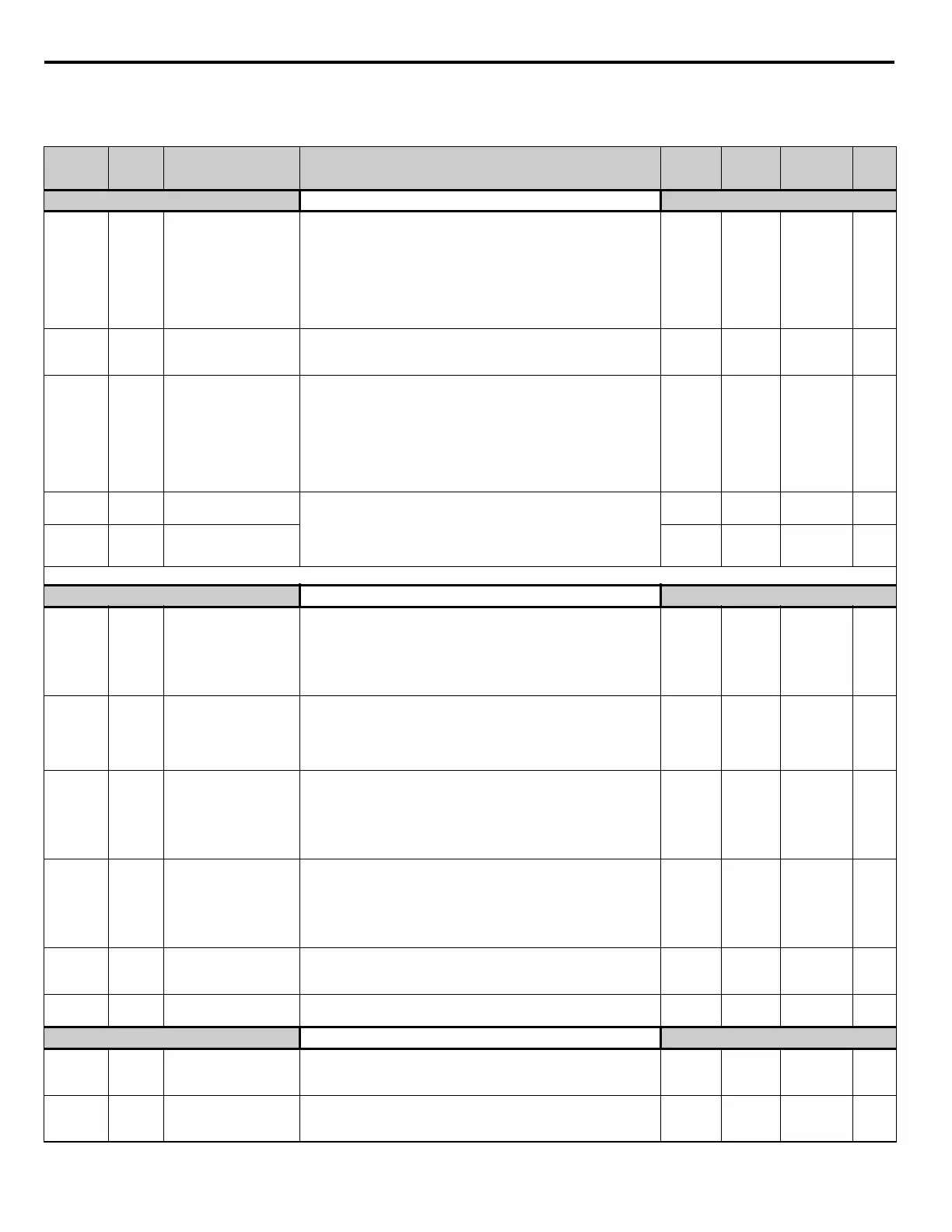
Table 1 Parameter List
Parameter
No.
Modbus
Address
Parameter Name
Digital Operator
Display
Description
Setting
Range
Factory
Setting
Menu
Location
Page
No.
Initialization
A1-00
0100H
Language Selection
Select Language
Language selection for digital operator display.
0: English
2: Deutsch
3: Francais
4: Italiano
5: Espanol
6: Portugues
*Not returned to factory setting by initialization
0 to 6 0 Programming
8
A1-01
0101H
Access Level Selection
Access Level
This setting determines which parameters are accessible.
0: Operation Only
2: Advanced Level
0 or 2 2 Programming
8
A1-03 0103H
Initialize Parameters
Init Parameters
Used to return all parameters to their factory or user setting.
0: No Initialize
1110: User Initialize (The user must set their own parameter default
values and then parameter o2-03 must be set to “1” to save them. If the
parameter values are changed after o2-03 is set to “1,” the user default
values can be restored by setting A1-03 to 1110.)
2220: 2-Wire Initial
3330: 3-Wire Initial
0 to 3330 0 Programming
8
A1-04 0104H
Password 1
Enter Password
When the value set into A1-04 does NOT match the value set into A1-
05, parameters A1-01 thru A1-03 cannot be changed. All other
parameters as determined by A1-01 can be changed. Parameter A1-05
can be accessed by pressing the MENU key while holding the RESET
key.
0 to 9999 0 Programming
99
A1-05 0105H
Password 2
Select Password
0 to 9999 0 Programming 9
Denotes that parameter can be changed when the drive is running. * Menu location is Pump Quick Setup when b5-01=1, and Programming when b5-01=0.
Sequence
b1-01 0180H
Frequency Reference
Selection
Reference Source
Selects the speed command (frequency reference) input source.
0: Operator - Digital preset speed d1-01
1: Terminals - Analog Input Terminal A1 (or Terminal A2 see
parameter H3-13)
2: Serial Com - RS-485 terminals R+, R-, S+ and S-
3: Option PCB - Option board connected at 2CN
0 to 3 0
Pump Quick
Setup
10
b1-02 0181H
Run Command Selection
Run Source
Selects the run command input source.
0: Operator - “Hand” and “Off” keys on digital operator
1: Terminals - Contact Closure on Terminal S1
2: Serial Com - RS-485 terminals R+, R-, S+ and S-
3: Option PCB - Option board connected at 2CN
0 to 3 0
Pump Quick
Setup
12
b1-03 0182H
Stopping Method
Selection
Stopping Method
Selects the stopping method when the run command is removed.
0: Ramp to Stop
1: Coast to Stop
2: DC Injection to Stop
3: Coast w/Timer (A new run command is ignored if input before the
time in C1-02 expires.)
0 to 3 0 Programming
15
b1-07 0186H
Local/Remote Run
Selection
LOC/REM RUN Sel
0: Cycle External RUN - If the run command is closed when switching
from hand (local) mode to auto (remote) mode, the Drive will not run.
1: Accept External RUN - If the run command is closed when
switching from hand (local) mode to auto (remote) mode, the Drive
WILL run.
Note: Used with LCD Operator only.
0 or 1 0 Programming —
b1-08 0187H
Run Command Selection
During Program
RUN CMD at PRG
0: Disabled - Run command accepted only in the operation menu.
1: Enabled - Run command accepted in all menus (except when b1-02
= 0).
0 or 1 0 Programming —
b1-11 010FH
Drive Delay Time Setting
Wait to Run Time
After a run command, Drive output will start after this delay time. 0 to 600 0 sec Programming 17
DC Braking
b2-01 0189H
DC Injection Braking
Start Frequency
DCInj Start Freq
Sets the frequency at which DC injection braking starts when ramp to
stop (b1-03 = 0) is selected. If b2-01< E1-09, DC injection braking
starts at E1-09.
0.0 to 10.0 0.5 Hz Programming
18
b2-02 018AH
DC Injection Braking
Current
DCInj Current
Selects the DC injection braking current as a percentage of the Drive
rated current.
0 to 100 50% Programming
18

 Loading...


