198 YASKAWA TM.iQp.02 iQpump Drive Programming Manual
Monitor List
Table 2 Monitor List
Parameter No.
Modbus
Address
Parameter Name Digital
Operator Display
Description
Monitor
U1-01 0040H
Auto Setpoint Reference
Auto: Setpoint
Auto Setpoint Reference (speed command) monitor when in auto mode, frequency reference
(speed command) setting location when in hand mode. Units changeable via P1-02.
U1-02 0041H
Output Frequency
Output Freq
Output frequency monitor in Hz.
U1-03 0042H
Output Current
Output Current
Output current monitor.
U1-06 0045H
Output Voltage
Output Voltage
Displays Drive output voltage.
U1-07 0046H
DC Bus Voltage
DC Bus Voltage
Displays DC bus voltage.
U1-08 0047H
Output Power
Output kWatts
Displays Drive output power.
U1-10 0049H
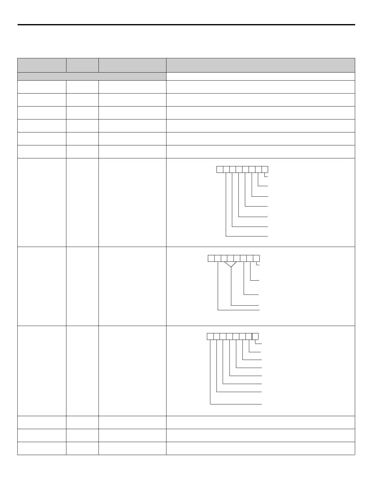
Input Terminal Status
Input Term Sts
Displays Drive input terminal status.
U1-11 004AH
Output Terminal Status
Output Term Sts
Output terminal ON/OFF check.
U1-12 004BH
Drive Operation Status
Int Ctl Sts 1
U1-13 004CH
Cumulative Operation Time
Elapsed Time
Displays total operating or power-on time of the Drive.
U1-14 004DH
Software Number
FLASH ID
Displays Drive's software number.
U1-15 004EH
Terminal A1 Input Voltage
Term A1 Level
Displays the input voltage on Terminal A1, as a percentage of 10 Vdc.
0
1: FWD. run
(Terminal S1) is ON.
1: REV. run
(Terminal S2) is ON.
1: Multi-function input 1
(Terminal S3) is ON.
1: Multi-function input 2
(Terminal S4) is ON.
1: Multi-function input 3
(Terminal S5) is ON.
1: Multi-function input 4
(Terminal S6) is ON.
1: Multi-function input 5
(Terminal S7) is ON.
0 0 0 0 0 0 0
1: Multi-function Contact 1
output 1 (Terminal M1-M2) is
ON.
1:Multi-function Contact 2
output 1 (Terminal M3-M4) is
ON.
Not used
Not used
1:Fault output
(Terminal MA/MB-MC) is
ON.
0 0 0 0 0 0 0 0
1: During running
1: During zero speed
1: During reverse
1: During reset signal input
1: During speed agree
1: Drive operation ready
1: During fault detection
(Minor fault)
1: During fault detection
(Major fault)
0 0 0 0 0 0 0 0

 Loading...


