40 YASKAWA TM.iQp.02 iQpump Drive Programming Manual
◆ E1 V/f Pattern
■ E1-01 Input Voltage Setting
Setting Ranges: 155.0 V to 255.0 V (208 V/240 V Models)
310.0 V to 510.0 V (480 V Models)
Factory Defaults: 208.0 V (208 V Models)
240.0 V (240 V Models)
480.0 V (480 V Models)
Set the Input Voltage parameter (E1-01) to the nominal voltage of the connected AC power supply. This parameter adjusts the levels of
some protective features of the iQpump drive (i.e. Overvoltage, Stall Prevention, etc.). E1-01 also serves as the Maximum/Base Voltage
used by the Preset V/Hz curves (E1-03 = 0 to D).
■ E1-03 V/f Pattern Selection
The iQpump drive operates utilizing a set V/f pattern to determine the appropriate output voltage level for each commanded speed. There
are 14 different preset V/f patterns to select from with varying voltage profiles, saturation levels (frequency at which maximum voltage is
reached), and maximum frequencies.
There are also settings for Custom V/f patterns that will allow the programmer to manually set (“Customize”) the V/f pattern using
parameters E1-04 through E1-13.
Using parameter E1-03, the programmer can select one of the preset V/f patterns or chose between a custom V/f pattern with an upper
voltage limit (E1-03 = “F: Custom V/f”) and a custom V/f pattern without a voltage limit (E1-03 = “FF: Custom w/o limit”).
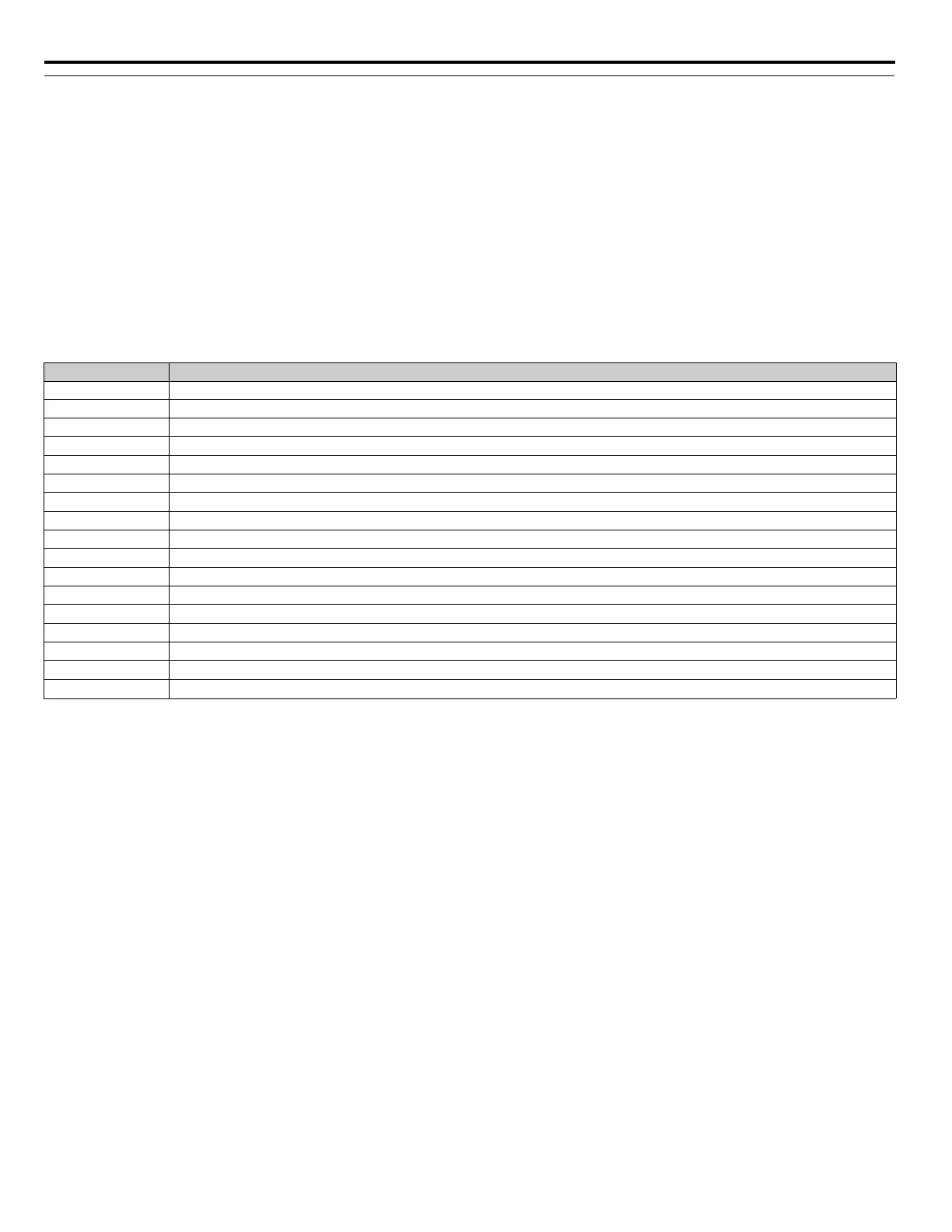
Setting Description
050 Hz
1 60 Hz Saturation
2 50 Hz Saturation
372 Hz
450 Hz VT1
550 Hz VT2
660 Hz VT1
760 Hz VT2
850 Hz HST1
950 Hz HST2
A60 Hz HST1
B60 Hz HST2
C90 Hz
D 120 Hz
E 180 Hz (invalid - OPE2 fault will occur)
FCustom V/f (factory default, with parameter values per setting 1)
FF Custom w/o limit

 Loading...


