178 YASKAWA TM.iQp.02 iQpump Drive Programming Manual
Preset Reference
d1-01
0280H
Setpoint Reference 1
Setpoint 1
Digital preset setpoint reference 1. Used when b1-01 = 0 and when in
“hand” mode. Setting units are affected by P1-02.
1 to P1-03
Va l ue
0 Programming
36
d1-02
0281H
Setpoint Reference 2
Setpoint 2
Digital preset setpoint reference 2. Selected via multi-function input
terminals. Setting units are affected by P1-02.
0 Programming
36
d1-03
0282H
Setpoint Reference 3
Setpoint 3
Digital preset setpoint reference 3. Selected via multi-function input
terminals. Setting units are affected by P1-02.
0 Programming
36
d1-04
0283H
Setpoint Reference 4
Setpoint 4
Digital preset setpoint reference 4. Selected via multi-function input
terminals. Setting units are affected by P1-02.
0 Programming
36
d1-17
0292H
Jog Frequency Reference
Jog Reference
Jog reference used when a jog is selected via the LCD operator keypad.
This parameter is not available with the HOA operator. Setting units
are affected by o1-03.
0 Programming
37
Denotes that parameter can be changed when the drive is running.
Reference Limits
d2-01 0289H
Frequency Reference
Upper Limit
Ref Upper Limit
Determines maximum speed command, set as a percentage of
parameter E1-04. If speed command is above this value, actual Drive
speed will be limited to this value. This parameter applies to all speed
command sources.
0.0 to
110.0
100.0% Programming
38
d2-02 028AH
Frequency Reference
Lower Limit
Ref Lower Limit
Determines minimum speed command, set as a percentage of
parameter E1-04. If speed command is below this value, actual Drive
speed will be set to this value. This parameter applies to all speed
command sources.
0.0 to
110.0
0.0% Programming
38
d2-03 0293H
Master Speed Reference
Lower Limit
Ref1 Lower Limit
Determines the minimum speed command, set as a percentage of
parameter E1-04. If speed command is below this value, actual Drive
speed will be set to this value. This parameter only applies
to analog inputs A1 and A2.
0.0 to
110.0
0.0% Programming
38
Jump Frequencies
d3-01 0294H
Jump Frequency 1
Jump Freq 1
These parameters allow programming of up to three prohibited
frequency points for eliminating problems with resonant vibration of
the motor / machine. This feature does not actually eliminate the
selected frequency values, but will accelerate and decelerate the motor
through the prohibited bandwidth.
0.0 to
200.0
0.0 Hz Programming
39
d3-02 0295H
Jump Frequency 2
Jump Freq 2
0.0 Hz Programming 39
d3-03 0296H
Jump Frequency 3
Jump Freq 3
0.0 Hz Programming 39
d3-04 0297H
Jump Frequency Width
Jump Bandwidth
This parameter determines the width of the deadband around each
selected prohibited frequency point. A setting of “1.0” will result in a
deadband of +/- 1.0 Hz.
0.0 to 20.0 1.0 Hz Programming
39
V/F Pattern
E1-01 0300H
Input Voltage Setting
Input Voltage
Set to the nominal voltage of the incoming line.
155 to
255.0
(240V)
310 to
510.0
(480V)
240 V
480 V
Programming
40
E1-03 0302H
V/F Pattern Selection
V/F Selection
0: 50 Hz
1: 60 Hz Saturation
2: 50 Hz Saturation
3: 72 Hz
4: 50 Hz VT1
5: 50 Hz VT2
6: 60 Hz VT1
7: 60 Hz VT2
8: 50 Hz HST1
9: 50 Hz HST2
A: 60 Hz HST1
B: 60 Hz HST2
C: 90 Hz
D: 120 Hz
F: Custom V/F
FF: Custom w/o limit
0 to FF F Programming
40
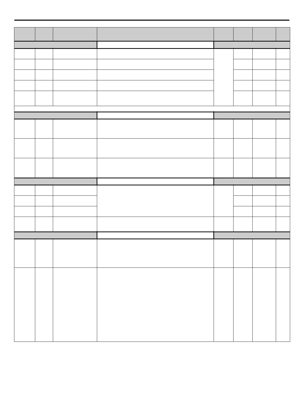
Parameter
No.
Modbus
Address
Parameter Name
Digital Operator
Display
Description
Setting
Range
Factory
Setting
Menu
Location
Page
No.

 Loading...


