52 YASKAWA TOEPYAIL1E01A YASKAWA AC Drive L1000E Quick Start Guide
4 Start-Up Programming
4 Start-Up Programming
LED Monitor JVOP-184 shows information about drive status including faults and alarms. The optional digital operator
JVOP-180, can be used to adjust parameters as required.
◆ LED Monitor JVOP-184
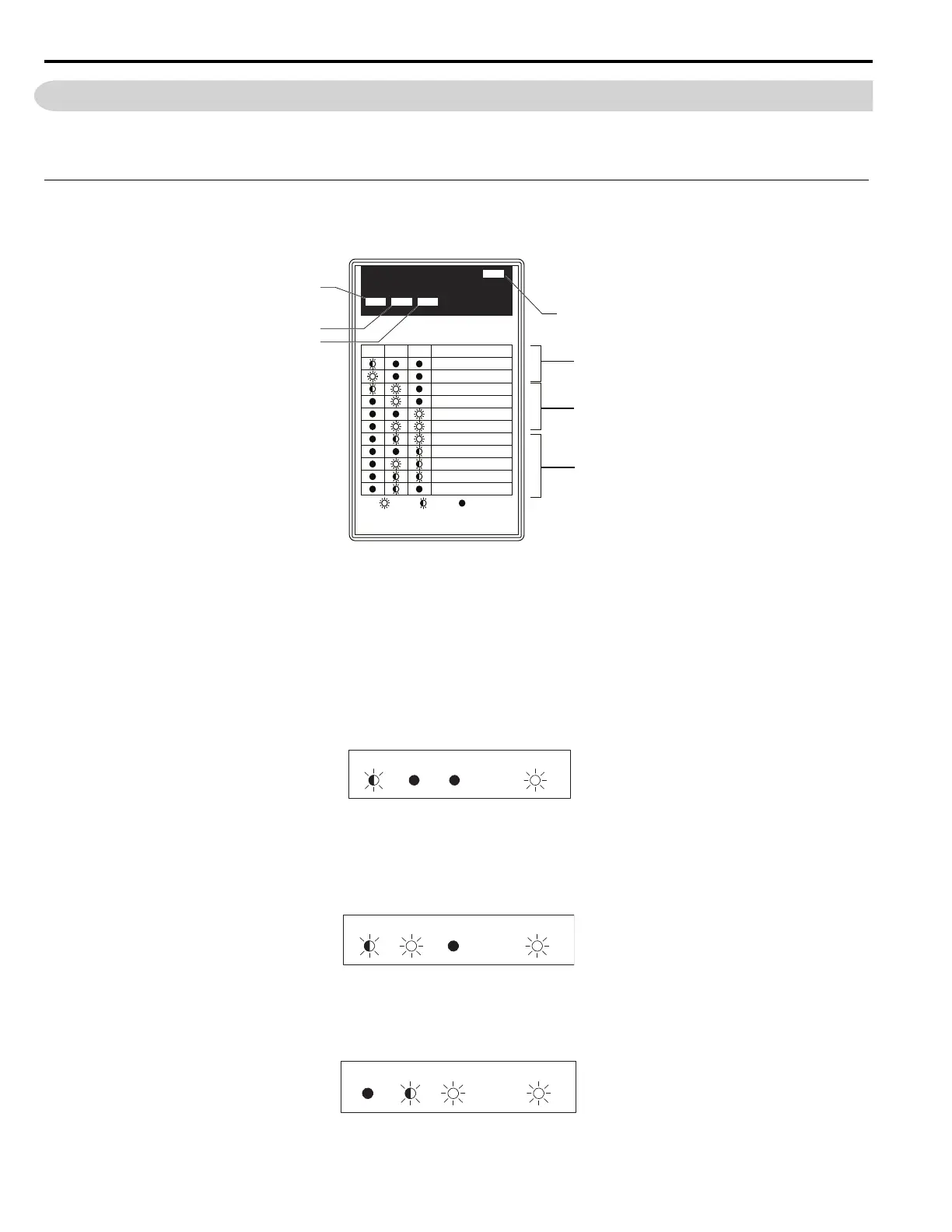
The LED monitor indicates operation status by combinations of the LEDs (LIGHT/BLINK/OFF) at RUN, DS1, and DS2.
Figure 31
Figure 31 LED Monitor Component Names
■ LED Display Examples
Normal Operation
Figure 32 shows the LED display when the drive is ready and no FWD/REV signal is active.
Figure 32
Figure 32 Normal Operation LED
Alarm
Figure 33 shows the LED display when a minor fault occurs. Refer to Troubleshooting on page 130 and take appropriate
countermeasures.
Figure 33
Figure 33 Alarm LED
Fault
Figure 34 shows the LED display when an oV or UV fault has occurred.
Figure 34
Figure 34 Fault LED
A – PWR LED (Red) E – DS2 LED (Green)
B – Drive Status Indications F – DS1 LED (Green)
C – Alarm Indications G – RUN LED (Green)
D – Fault Indications
PWRLED MONITOR JVOP-184
RUN DS1 DS2
RUN DS1 DS2 STATUS
READY
RUN
ALARM(RUN)
PGOH,LT
BB,HBB
EF,SE
Other Fault
OV,UV
OH,OL
OC,GF,SC,PGO
CPF,OFA,OFB,OFC
:LIGHT :BLINK :LIGHT OFF
A
G
F
E
B
C
D
RUN DS1 DS2 POWER