4 Start-Up Programming
YASK AWA TOEPYAIL1E01A YASKAWA AC Drive L1000E Quick Start Guide 65
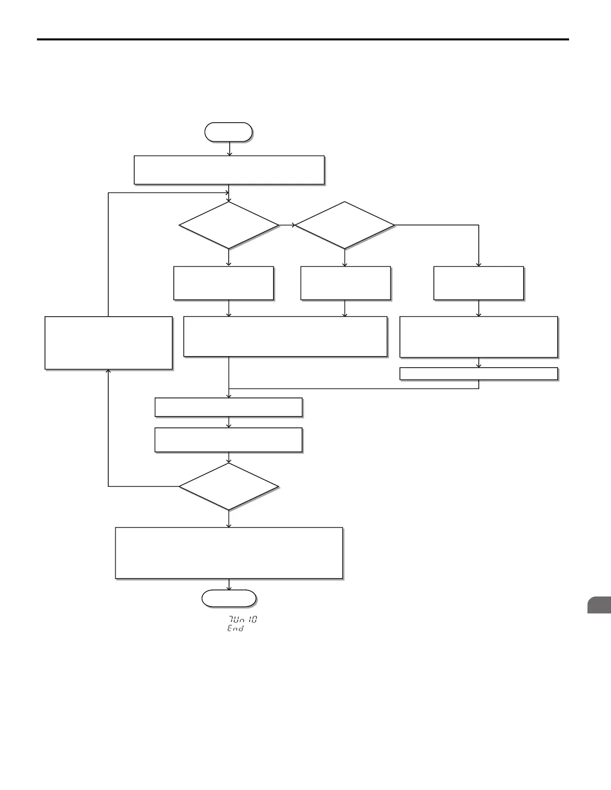
■ Flowchart B: Auto-Tuning for Induction Motors
The flowchart below covers Auto-Tuning for induction motors operating with V/f Control, Open Loop Vector Control, or
Closed Loop Vector Control.
Figure 42 Auto-Tuning for Induction Motors
<1> If an LED operator is used, the display shows “ ”.
<2> If an LED operator is used, the display shows “ ”.
START
Set terminals H1 and H2 if the Safe Disable function is used.
Enter the data in to T1- parameters as indicated on the
display.
Is the Control Mode
V/f Control ?
Apply the brake if it was released during Auto-tuning.
FINISH
Can the motor
rotate freely?
Select Stationary Auto-Tuning
for Terminal Resistance only,
T1-01 = 2.
Select Stationary
Auto-Tuning 1 or 2
T1-01 = 1 or 4.
No
A1-02=2 or 3
Yes
A1-02=0
No
Yes
(Ropes removed)
Select Rotational
Auto-Tuning
T1-01 = 0.
Press the Up key until “Tuning Ready” is displayed.
Enter the data in to T1- parameters as
indicated on the display.
Press the Up key until “Tuning Ready” is
displayed.
<1>
Release the Brake.
Close the motor contactor(s).
Press the Run key on the digital operator
and wait until Auto-Tuning is finished.
Set the Baseblock input (H1- = 8/9) if used.
Tuning
Successful?
Refer to
Remove the source of Fault/Alarm
and repeat Auto Tuning.
Open terminals H1-HC and H2-HC if used during the normal sequence.
Open the motor contactor(s).
Open the Baseblock input (H1- = 8/9) if used.
No
(Alarm or Fault code
displayed
Yes
(“Entry Accepted”
displayed) <2>
<1>
Auto-Tuning Fault Detection
on page 138.
YEA_comm
on
 Loading...


