5.8 L: Protection Functions
YASKAWA EUROPE SIEP YASKAWA AC Drive L1000V Technical Manual 143
Parameter Details
5
Setting 3: oL3, oL4 at speed agree (Fault)
Overtorque detection is active only when the output speed is equal to the speed reference, i.e., no detection during
acceleration and deceleration. The operation is stopped and an oL3 or oL4 fault is triggered.
Setting 4: oL3, oL4 at run (Fault)
Overtorque detection works as long as a Up/Down command is active. Operation stops and an oL3 or oL4 fault is
triggered.
Setting 5: UL3, UL4 at speed agree (Alarm)
Undertorque detection is active only when the output speed is equal to the speed reference, i.e., no detection during
acceleration and deceleration. The operation continues after detection and an oL3 or oL4 alarm is triggered.
Setting 6: UL3, UL4 at run (Alarm)
Undertorque detection works as long as the Up/Down command is active. The operation continues after detection and an
oL3 or oL4 alarm is triggered.
Setting 7: UL3, UL4 at speed agree (Fault)
Undertorque detection is active only when the output speed is equal to the speed reference, i.e., no detection during
acceleration and deceleration. The operation is stopped and an oL3 or oL4 fault is triggered.
Setting 8: UL3, UL4 at run (Fault)
Undertorque detection works as long as a Up/Down command is active. Operation stops and an oL3 or oL4 fault is
triggered.
n
L6-02, L6-05: Torque Detection Level 1, 2
These parameters set the detection levels for the torque detection functions 1 and 2. In V/f control mode, these levels are
set as a percentage of the drive rated output current, while in vector control modes these levels are set as a percentage of
the motor rated torque.
n
L6-03, L6-06: Torque Detection Time 1, 2
These parameters determine the time required to trigger an alarm or fault after exceeding the levels in L6-02 and L6-05.
u L7: Torque Limit
The torque limit function can be used to limit the torque in each of the four quadrants individually and thereby protect the
elevator. It can be used in vector control modes. The limit can be set by parameters. A digital output programmed for
“During torque limit” (H2-01 through H2-05 = 30) will be switched when the drive is operating at the torque limit.
n
Setting Torque Limits
The torque limits are defined by parameters L7-01 to L7-04 for each of the four operation quadrants. Figure 5.30 shows
which of the limit settings is applied in each quadrant.
Note: The maximum output torque is ultimately limited by the drive output current. Output torque will not exceed the limit set for the
drive rated current, even if the torque limits are set to higher values.
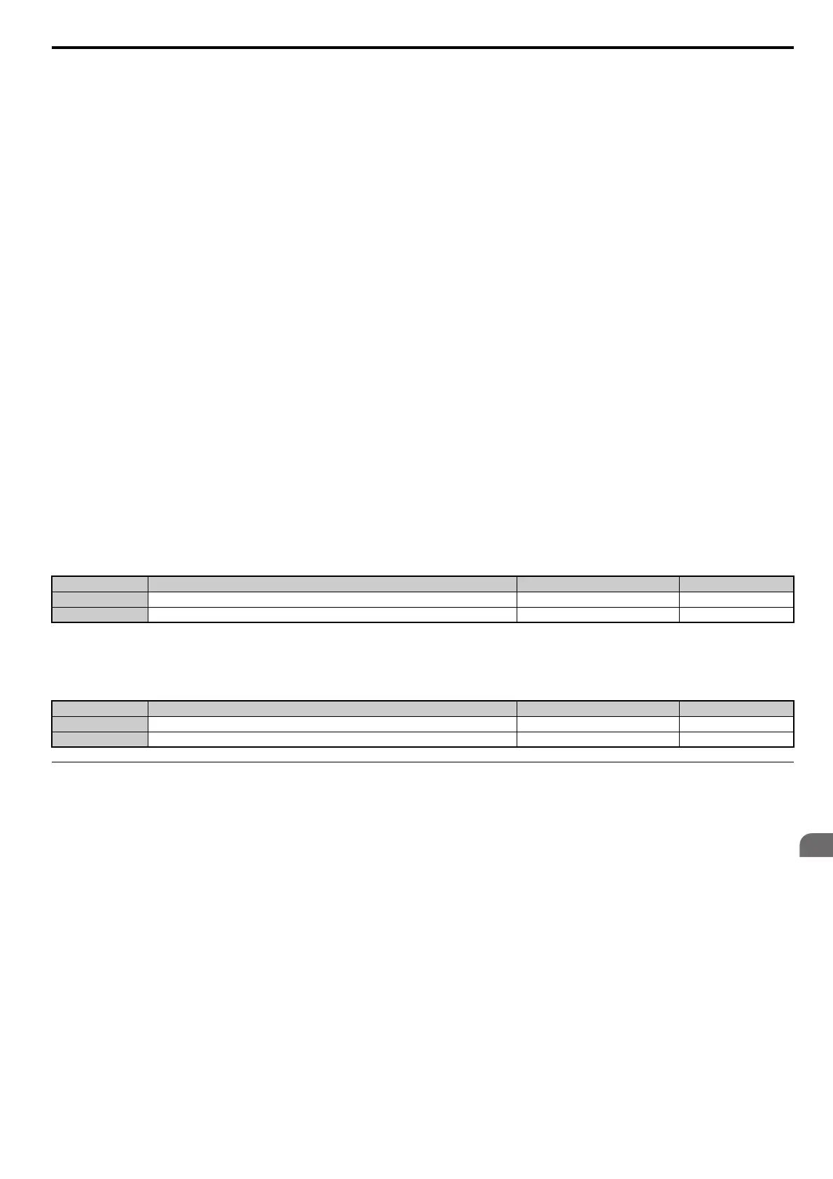
No. Name Setting Range Default
L6-02 Torque Detection Level 1 0 to 300% 150%
L6-05 Torque Detection Level 2 0 to 300% 150%
No. Name Setting Range Default
L6-03 Torque Detection Time 1 0.0 to 10.0 s 0.1 s
L6-06 Torque Detection Time 2 0.0 to 10.0 s 0.1 s
 Loading...