Where cycle time IT) is determined, values Ip, tr, 4. 4 SERVOMOTOR FREQUENCY
) tf satisfying the formula above, should be specified.
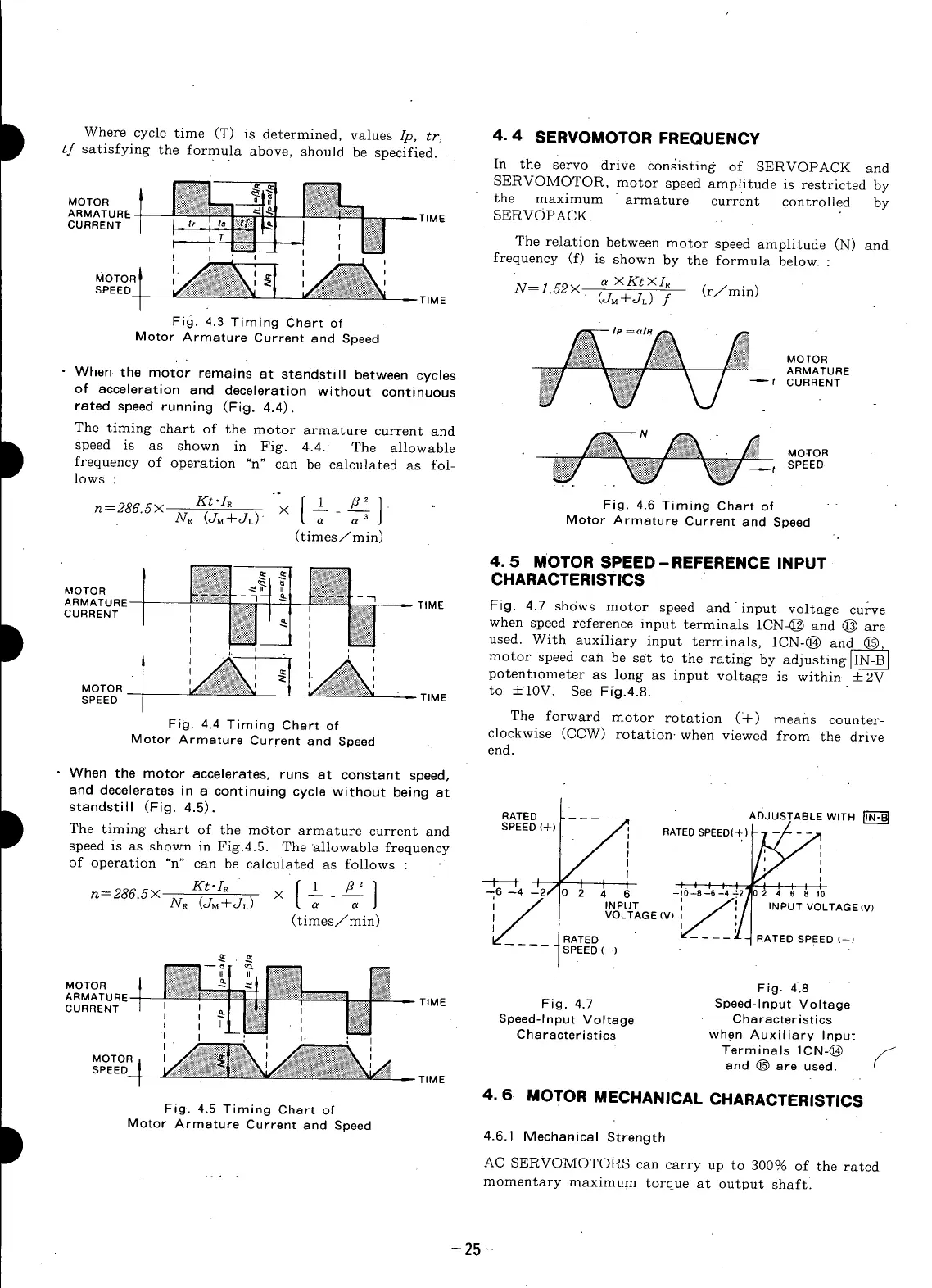
In the serve drive consisting of SERVOPACK and
' SERVOMOTOR, motor speed amplitude is restricted by
| _ the maximum armature current controlled by
MOTOR
1
SERV©PACK.
ARMATURE = T_ME
CURRENT I l ,, I " Itml 1-_I I ; I_!
I" ; T I'J_l Trl ] I I_;I The relation between motor speed amplitude IN) and
t_--_ _ _ _ frequency If) is shown by the formula below :
MOTOR _ _;_'¢;.'_ l I " " "
I"_' ;_g!}:k ; _ I N = 1.52 X (r/min)
SPEED I ...._'_'_':_"_ (JM+JL) f
I/;Y(_:_:,::,;:_:,_._'lll I TIME
I
Fig. 4.3 Timing Chart of _ Ip=ala_
Motor Armature Current and Speed
When the motor remains at standstill between cycles _,_ ;!_;_ --t ARMATURE
. j L/
of acceleration and deceleration without continuous f_ !'_
' o
rated speed running (Fig. 4.4).
The timing chart of the motor armature current and N - ._
speed is as shown in Fig. 4.4. The allowable . . /_:_;_ MOTOR
of "n" be calculated fol- _;_< _!_:_y _] _t SPEED
lows:frequencyoperation can as __ . _
Kt.IR [1 _)21. Fig. 4.6 Timing Chert of
n=286"5X NR ('-]M+JL)" X a- _-_ Motor Armature Current end Speed
(times/min)
4.5 MOTOR SPEED-REFERENCE INPUT
MOTOR _ -_
_;_ _ - _ _ -
"_:_ } l I _; TIME Fig. 4.7 shows motor speed and input voltage curve
ARMATURE
I
_!:*:_!iI [ i:_!_ when speed reference input terminals 1CN-@ and @ areCURRENT ( ;_ _ , _:_
i _:,_:;_1 II I N_: used. With auxiliary input terminals, 1CN-@ andr= _
I ' I I motor speed can be set to the rating by adjusting]iN-B]
_ i _ i potentiometer as long as input voltage is within +2V
MOTOR TIME to +10V. See Fig.4.8.
SPEED I The forward motor rotation (4-) means counter-
Fig. 4.4 Timing Chart of clockwise (CCW) rotation-when viewed from the drive
Motor Armature Current and Speed end.
• When the motor accelerates, runs at constant speed,
and decelerates in a continuing cycle without being at
standstill (Fig. 4.5). RATED ADJUSTABLE WITH
The timing chart of the motor armature current and SPEED (+) / I RATEDSPEED(+) -- -- ,
speed is as shown in Fig.4.5. The allowable frequency I
of operation "n" can be calculated as follows : t
Kt'I, [ 1 [?' ] t I /2/ I I t , ' , , ,. ' ....--6--4 0 2 4 6 -10-8-6-4-21 } 4 6 8 1'0
n=286.5X N. (g_+JL) × [ -- - - J i / INPUT ', /:/ INPUT VOLTAGE(V)
a a VOLTAGE IV) _ /,[
(times/rain) I___ __II ' :
' _-----;_- _ATED SPEED(-)
RATED
SPEED (--)
II II
MOTOR I Fig. 4.8
ARMATURE I i J I_!_!! , I_;_I = TIME Fig. 4.7 Speed-Input Voltage
CURRENT - _ a _ Speed-lnput Voltage Characteristics
i _l_'_il • _ when Auxiliary Input
I _ _i-,i._l II Characteristics .
I • I
' _ o _ _ Terminals 1CN-@ /
and(_)are.used.
MOTOR I I
SPEED _ _TIME "
I 4.6 MOTORMECHANICALCHARACTERISTICS
Fig. 4.5 Timing Chert of
Motor Armature Current and Speed 4.6.1 Mechanical Strength
AC SERVOMOTORS can carry up to 300% of the rated
-" - momentary maximum torque at output shaft:
-25-
 Loading...


