Am
10.2 CHARACTERISTICS AT THE TIME Table 10.3 Overshoot and Undershoot
OF DELIVERY at Stop Response
1
The SERVOPACK has been factory-adjusted as Type CACR- zJNov/NR.X 100 z_Nuo/NRX 100
follows :
SR03BB
(1) Speed reference input SERVOMOTOR speed
ratio (no load) (Fig. 10.1) SR05BB
SPEED (r/min) SR07BB
RATED __......... _ SR10BB
s_o+p
SR15BB 5 % max 5 % max
SR20BB
--6V 0j_ , SPEED INPUT
- (ACROSS1ca-@ SR30BB
; /I +6V and@)
SR44BB
SR60BB
___ RATED
r rSPEED (--)
.all
Fig. 10.1 Speed Reference Input- I
SERVOMOTOR Speed Ratio 10.3 READJUSTMENT
"ql
(2) Speed Regulation (Fig. 10.2) The SERVOPACK has been adjusted at the factory to
Speed regulation zlN z3n: obtain optimum characteristics and readjustment is
normally unnecessary. If adjustment is required depend-
z3N x 100 % < 0.03 % ing on the use, readjust the SERVOPACK referring to
NR Table 10.14. (Do not temper with potentiometers.)
zfln
X 100%___0.015%
NR
,din
10.4 ADJUSTMENT PROCEDURES I
SPEED(r/rain) NR: RATED Fig. 10.4 shows the arrangement of potentiometers,
__'-_- i SPEED and terminals for checking waveforms; Table 10.11
R N shows the specifications of the check pin (CH); and
Table 10.15 lists check terminals and functions.
Adjust the potentiometers, observing the specified
check locations. (Potentiometers should not be tampered
--+3_1 ,[--_. MOTOR with.) Fig. 10.5 shows waveforms at the respective
MOTOR RATED f CURRENT
CURRENT check terminals for step responses at no load.
10.2 SpeedRegulation I
Fig.
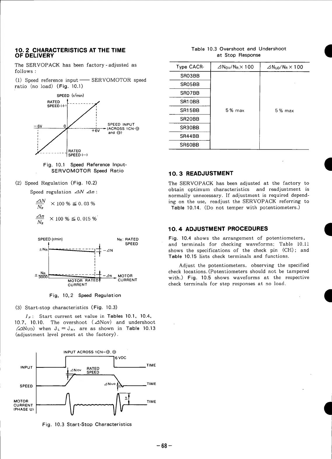
(3) Start-stop characteristics (Fig. 10.3)
Ip: Start current set value in Tables 10.1, 10.4,
10.7, 10.10. The overshoot (z_Nov) and undershoot
(_z_NuD) when JL=JM, are as shown in Table 10.13
(adjustment level preset at the factory).
INPUT ACROSS 1CN-@, @
_/_ 6 VDC
TIME
INPUT ov RATED
SPEED
SPEED z_Nu_ TIME
MOTOR %_ _j,,_ __]'_'-_ TIME I
CURRENT --_- -- -
(PHASE U)
Fig. 10.3 Start-Stop Characteristics
-68-
 Loading...


