(4) D series
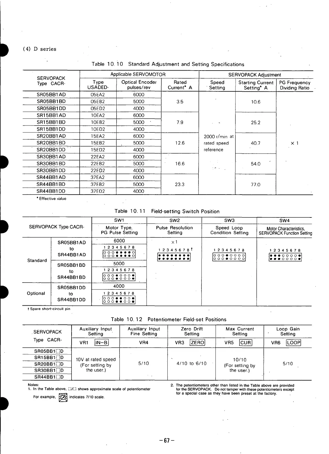
Table 10.10 Standard Adjustment and Setting Specifications
Applicable SERVOMOTOR SERVOPACK Adjustment
SERVOPACK
Type CACR- Type Optical Encoder Rated Speed Starting Current PG Frequency
USADED- pulses/rev Current* A " Setting Setting* A Dividing Ratio
SR05BB1AD 05EA2 6000
SR05BB1BD 05EB2 5000 3.5 10.6
SR05BB1DD 05ED2 4000
SR15BB1AD IOEA2 6000
SR15BB1BD lOEB2 5000 7.9 25.2
SR15BB1DD IOED2 4000
SR20BB1AD 15EA2 6000 2000 r/rain at
SR20BB1BD 15EB2 5000 12.6 ratedspeed 40.7 x 1
+ ,
SR20BB1DD 15ED2 4000 reference
SR30.BB1AD 22EA2 6000
SR30BB1BD 22EB2 5000 16.6 54.0
SR30BB1DD 22ED2 4000
SR44BB1AD 37EA2 6000
SR44BB1BD 37EB2 5000 23.3 77.0
SR44BB1DD 37ED2 4000
* Effective v'alue
Table 10.11 Field-setting Switch Position
SWl SW2 SW3 SW4
SERVOPACKType CACR- Motor Type, Pulse Resolution Speed Loop MotorCharacteristics,
PG Pulse Setting Setting Condition Setting SERVOPACK FunctionSettinc
SR05BB1AD 6000 x 1
to 1 2345678 1 2345678 t I 2345678 1 2345678
ooo....o J" " :1 io o o1 I" o° °'1
SR44BB1AD ooeooo coo oo ooo oo eo oo
Standard . • • • • • oo• oo •• oo
SR05BB1BD 5000
to 12345678
SR44BBIBD I°o°o°•ooe°°°:j
SROSBB1DD 4000
Optional to 1 2 3 4 5 6 7 8
SR44BBIDD oo°o•°°.•o ooo
1"Spare short-circuit pin
Table 10.12 Potentiometer Field-set Positions
Auxiliary Input Auxiliary Input Zero Drift Max Current Loop Gain
.SERVOPACK Setting Fine Setting Setting Setting Setting
Type CACR- VR1 _ VR4 VR3 _ VR5 _ VR6
SR05BB1E]D
SR15BB1[_]D 10V at rated speed 10/10
SR20BB1 [_]D (For setting by 5/10 4/10 to 6/10 (For setting by 5/10
SR3OBB1[_]D the user.) the user.)
SR44BB1 [_]D
Notes: 2. The potentiometers other than listed in the Table above are provided
1. In the Table above, [.I_/E] shows approximate scale of potentiometer for the SERVOPACK. Do not tamper with these potentiometers except
for a special case as they have been preset at the factory.
For example, I[:_a'._l indicates 7/10 scale.
-67 -
 Loading...


