10. ADJUSTMENT dl
I
10. 1 SETTINGS AT THE TIME OF DELIVERY
The SERVOPACK has been factory-adjusted as
follows :
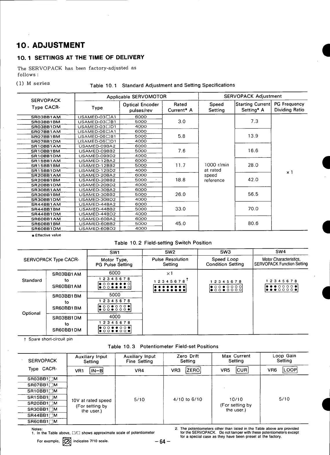
(1) M series Table 10.1 Standard Adjustment and Setting Specifications
Applicable SERVOMOTOR SERVOPACK Adjustment
SERVOPACK
Optical Encoder Rated Speed Starting Current PG Frequency
Type CACR- Type pulses/rev Current* A Setting Setting* A Dividing Ratio
SRO3BBIAM USAMED-O3[:]A1 6000
SRO3BB1 BM USAMED-O3r-] B 1 5000 3.0 7.3
SRO3BB 1 DM USAM ED-03 [-] D1 4000
SRO7BBIAM USAMED-O6r-]A 1 6000
SRO7BB 1BM USAM ED-06 [-] B 1 5000 5.8 13.9
SRO7BBIDM USAMED-O6r-Q D1 4000
SRIOBBIAM USAMED-O9BA2 6000
SR10BB1BM USAMED-09BB2 5000 7.6 16.6
SRIOBBIDM USAMED-O9BD2 4000
,rib
SR15BBIAM USAMED-12BA2 6000 m
SR15BB1BM USAMED-12BB2 5000 11.7 1000 r/rain 28.0
SR15BB1DM USAMED-12BD2 4000 at rated
xl
SR2OBB1 AM USAMED-2OBA2 6000 speed
SR2OBB 1 BM USAMED-2OBB2 5000 18.8 reference 42.0
SR2OBBIDM USAMED-2OBD2 4000
SR3OBB 1 AM USAM ED-3OBA2 6000
SR3OBB1 BM USAMED-3OBB2 5000 26.0 56.5
SR3OBBIDM USAMED-3OBD2 4000
SR448B1 AM USAMED-44BA2 6000
SR44BB1 BM USAMED-44BB2 5000 33.0 70.0
SR44BBIDM USAMED-448D2 4000
SR6OBBIAM USAMED-6OBA2 6000
SR6OBBIBM USAMED-60BB2 5000 45.0 80.6 m
I
SR6OBBIDM USAMED-6OBD2 4000
Effective value
Table 10.2 Field-setting Switch Position
SWl SW2 SW3 SW4
SERVOPACK Type CACR- Motor Type, Pulse Resolution Speed Loop Motor Characteristics,
PG Pulse Setting Setting Condition Setting SERV0PACK Function Setting
SR03BB1AM 6000 ×1
Standard to 1 2345678 1 23456781" 1 2345678 1 2345678
I: "°1 I: :1 I I I: I 9
SR60BBIAM °o°ee_.o.e _'._." "°o°e°°ooeoeo oo .eoO..oooOo.O.
SR03BB1 BM 5000
to 1 2345678
sR6oB81BM I:oo•°oo°o"1
Optional
SR03BB1 DM 4000
to 1 2345678
O000QO00
SR60BBIDM • o o • • o o •
1" Spare short-circuit pin
Table 10.3 Potentiometer Field-set Positions
Auxiliary Input Auxiliary Input Zero Drift Max Current Loop Gain
SERVOPACK Setting Fine Setting Setting Setting Setting
Type CACR- VR1 IT_ va4 vaaIZEROt VR5ICURI VR6ILOOPI
SR03BB1 [-]M
SR07BB1 [._]M
SR10BBI"_]M
SR15BBI[_]M
SR20BBI[-]M 10V at rated speed 5/10 4/10 to 6/10 10/10 5/10
° (For setting by (For setting by
IB
SR30BBIE_]M the user.) the user.)
SR44BB1 [*.]M
SR60BB1 [ _j M
Notes: 2. The potentiorneters other than listed in the Table above are provided
1. In the Table above, r_:]/[r] shows approximate scale of potentiometer for the SERVOPACK. Do not tamper with these potentiometers except
for a special case as they have been preset at the factory.
For example, _ indicates 7/10 scale. -- 64-
v-_
 Loading...


