6.9.2 Speed and Torque Measurement
SERVOPACKCONTROLOFF_ ON [
I
When an instrument is connected to measure speed and POWERSUPPLY
torque, make the connection as shown in Fig. 6.19, SERVOPACKMAIN OFF [ ON [
using a DC ammeter which is +_ 1 mA (both swing) POWERSUPPLy .1
load at fullscale voltage. SERVOONOFF ON
HOLDINGBRAKE OFF ON 1
_,_._ii BRAKERELEASE
_ICN-IO MONITOR (LINING) *2 -- *2 --
*6
r-n
--200ms TO 10SEC
iilCN.11 SPEED REFERENCE 0V
_!_ soov
/ I\
MOTORRUNNI
Fig. 6.19 Speed and Torque [-to_[ '
Measurement .
I /
200ms t0+t
OR MORE
• Torque monitor output (ICN-9): +-3.0v +--10%/100% Fig. 6.20 Brake Timing i_
torque
1
Speed monitor output (1CN-10):
M, F, D series--+-4.0V __5%/1000r/min Timming
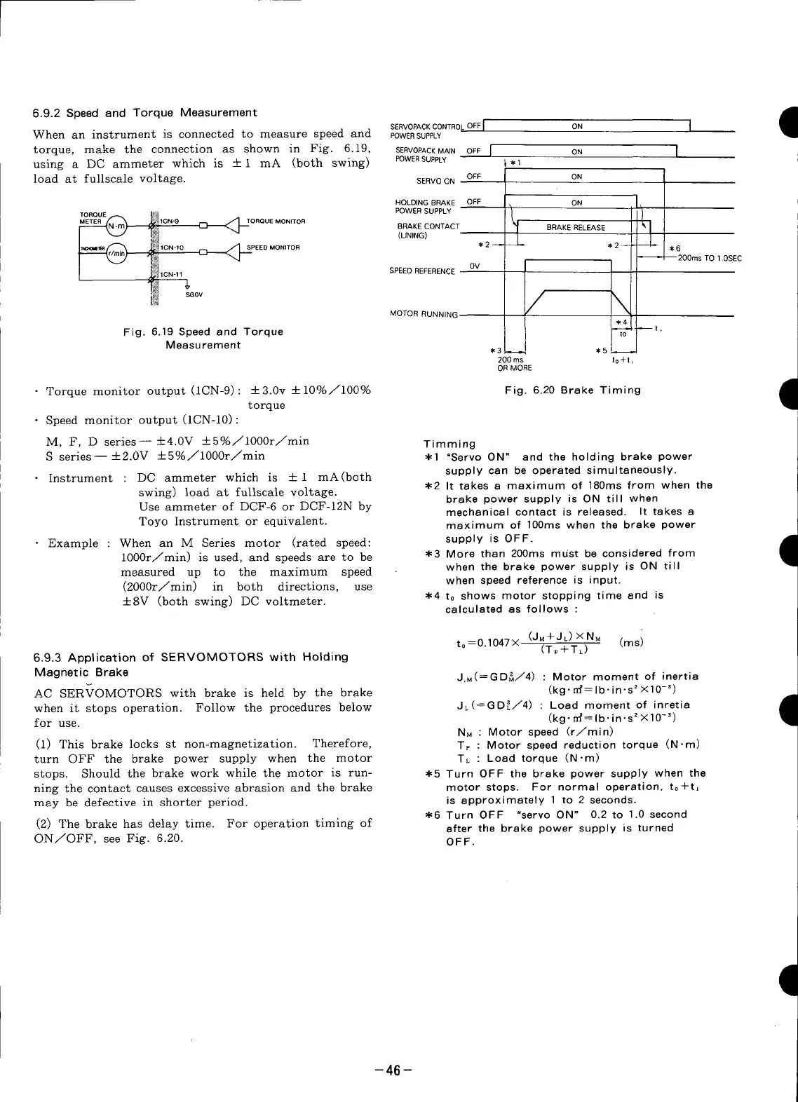
S series---I-2.0V +5%/1000r/min *1 "Servo ON" and the holding brake power
Instrument : DC ammeter which is + 1 mA(both supply can be operated simultaneously.
swing) load at fullscale voltage. *2 It takes a maximum of 180ms from when the
brake power supply is ON till when
Use ammeter of DCF-6 or DCF-12N by mechanical contact is released. It takes a
Toyo Instrument or equivalent, maximum of 100ms when the brake power
• Example : When an M Series motor (rated speed: supply is OFF.
1000r/min) is used, and speeds are to be *3 More than 200ms must be considered from
I
measured up to the maximum speed when the brake power supply is ON till
when speed reference is input.
(2000r/min) in both directions, use
+-SV (both swing) DO voltmeter. .4 to shows motor stopping time and is
calculated as follows :
(JM+JL) ×NM (mS)
t° =0"1047× (Tp+TL)
6.9.3 Application of SERVOMOTORS with Holding
Magnetic Brake J.M(=GD_/4) : Motor moment of inertia
AC SERVOMOTORS with brake is held by the brake (kg "rrf=lb'in's2×10-3)
when it stops operation. Follow the procedures below JL(_GD_./4) : Load moment of inretia
for use. (kg"rrf=Ib'in's2× 10-3)
1
NM : Motor speed (r/min)
(1) This brake locks st non-magnetization. Therefore, Tp : Motor speed reduction torque (N.m)
turn OFF the brake power supply when the motor TL : Load torque (N-m)
stops. Should the brake work while the motor is run- .5 Turn OFF the brake power supply when the
ning the contact causes excessive abrasion and the brake motor stops. For normal operation, t0+t,
may be defective in shorter period, is approximately 1 to 2 seconds.
*6 Turn OFF "servo ON" 0.2 to 1.0 second
(2) The brake has delay time. For operation timing of after the brake power supply is turned
ON/OFF, see Fig. 6.20. OFF.
-46 -
 Loading...


