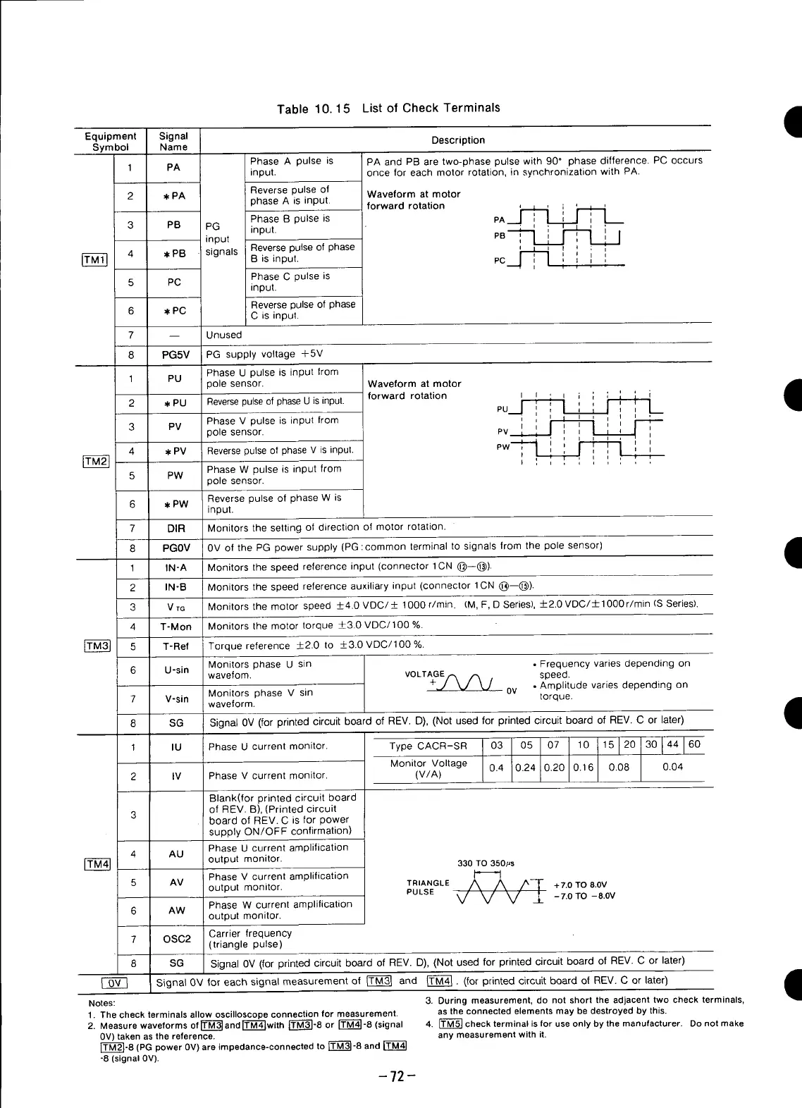
Table 10.15 List of Check Terminals
Equipment Signal Description
Symbol Name
Phase A pulse is PA and PB are two-phase pulse with 90" phase difference. PC occurs
1 PA input, once for each motor rotation, in synchronization with PA.
Reverse pulse of Waveform at motor
2 ,I,PA phase A is input, forward rotation
Phase B pulse is pA__.] I [____'_
3 PB PG input. ' ' ' '
' L L r--1 I
input PB ,, ,
4 *PB signals Reversepulse of phase , , r ; ,
Bisinput. PC i _, '
Phase C pulse is
5 PC input.
Reverse pulse of phase
6 W,PC C is input.
7 -- Unused
8 PG5V PG supply voltage +5V
Phase U pulse is input from
1 PU polesensor. Waveformatmotor
2 w,PU Reversepulseof phaseU isinput, forward rotation I m , _ , ,
I
_ ' ,
PU i I 1 Ii .I--,
PV Phase V pulse is input from , , _ , _ ,
3
_olesensor. PV I '* ' _ ' I ',
,,
i
, _ i i i ,
,,
PW
i
,,
',
4 w=PV Reversepulseof phase V is input. I I ! ! I
' , ; , , ,, ,
I ' i
Phase W pulse is input from
5 PW
3ole sensor.
Reverse pulse of phase W is
6 w,PW
input.
7 DIR Monitors the setting of direction of motor rotation.
8 PGOV 0V of the PG power supply (PG :common terminal to signals from the pole sensor)
,q
1 IN-A Monitors the speed reference input (connector 1CN (_)--(_).
2 IN-B Monitors the speed reference auxiliary input (connector 1CN (_)--(_)).
3 V TG Monitors the motor speed _+4.0 VDC/_+ 1000 r/rain. (M, F, D Series),-+-2.0VDC/± 1000 r/min (S Series).
4 T-Mon Monitors the motor torque _+3.0VDC/100 %.
r_ 5 T-Ref Torque reference +__2.0to _+3.0VDC/100 %.
Monitors phase U sin • Frequency varies depending on
6 U-sin wavefom. VOLTAGErx _ , speed.
• Amplitude varies depending on
Monitorsphase V sin 0v torque.
7 V-sin waveform. •
1
8 SG Signal 0V (for printed circuit board of REV. D), (Not used for printed circuit board of REV. C or later)
monitor. Type CACR-SR 03 05 07 10 15 120 30 144 160
1
IU
Phase
U
current
Monitor Voltage 0.4 0.24 0.20 0.16 0.08 0.04
2 IV Phase V current monitor. (V/A)
Blank(for printed circuit board
of REV. B), (Printed circuit
3 board of REV. C is for power
supply ON/OFF confirmation)
Phase U current amplification
4 AU
output monitor. 330 TO 350,us
Phase V current amplification I_ LI
5 AM output monitor. TRIANGLEVV -L' /A_ /Av/_7- +7.OTO8.0V
PULSE -7.0TO -8.0V
6 AW Phase W current amplification
output monitor.
7 OSC2 Carrier frequency
(triangle pulse)
8 SG Signal 0V (for printed circuit board of REV. D), (Not used for printed circuit board of REV. C or later)
I OV I Signal 0V for each signal measurement of ITM31 and ITM41. (for printed circuit board of REV. C or later) i
1
Notes: 3. During measurement, do not short the adjacent two check terminals,
1. Thecheck terminals allow oscilloscope connection for measurement, as the connected elementsmay be destroyed by this.
2. Measurewaveforms of r=_--_andr_'M"_with[_]-8 or _-8 (signal 4. _ check terminal isfor useonly by the manufacturer. Donot make
0V)taken asthe reference, any measurementwith it.
rT--_]-8 (PG power 0V)are impedance-connectedto rt--M-_-8and
-8 (signal 0V).
-72-
 Loading...


