1.4 Checking the LED Indications
1.4.1 Built-in Ethernet Module
1-5
1
Overview of Troubleshooting
1.4 Checking the LED Indications
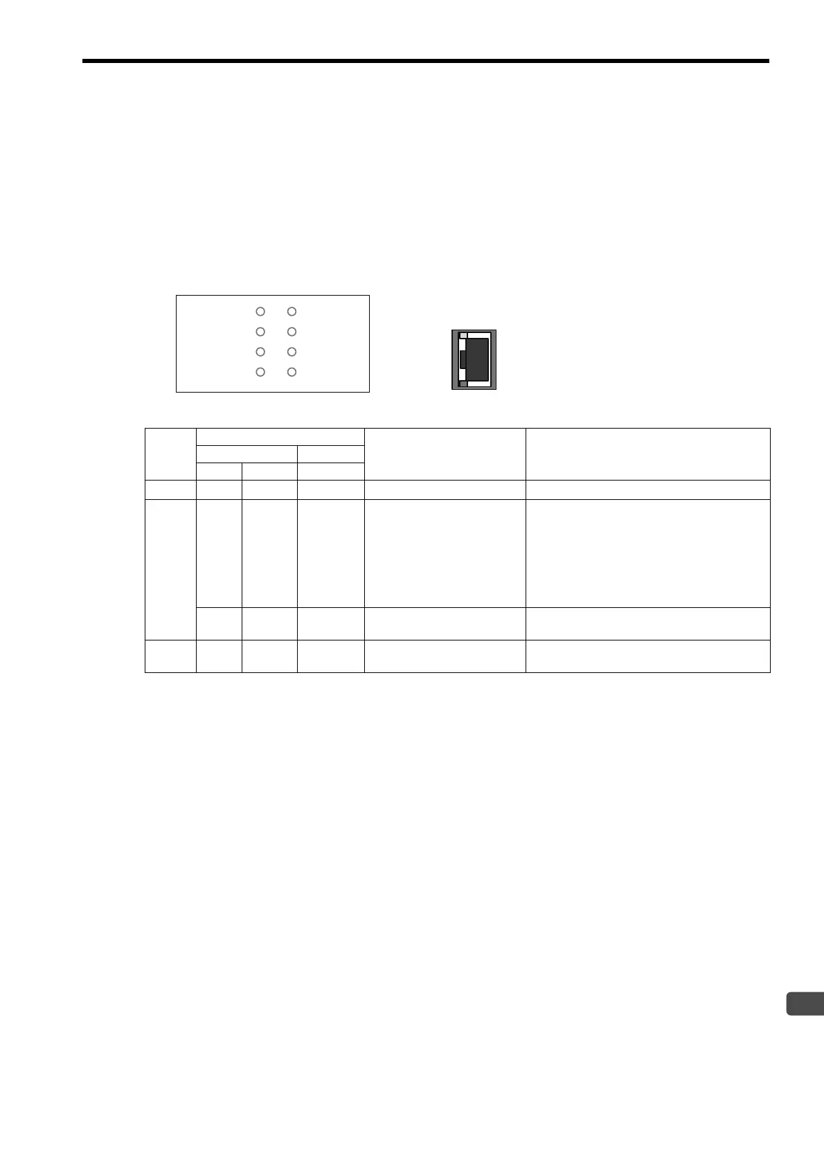
The error status and the details of the error can be checked using the LED indications at the front of the Ethernet
Module.
This section describes the patterns of LED indications and their details.
1.4.1 Built-in Ethernet Module
Note: Machine Controllers MP2300S, MP2400 and MP2310 incorporate a built-in Ethernet Module.
Note:
{
: Unlit,
z
: Lit,
: Flashing,
–
: Indefinite
LEDs at the front of the Ethernet Module
LEDs on the Ethernet Connector
RDY RUN
ALM
ERR
MTX
BAT
TRX
IP
Ethernet
LINK
100M
Cate-
gory
LED Indication
Indication RemedyModule Front Connector
IP TRX LINK
Normal
z
–
z
Operating normally Normal operation is in progress.
Alarm
–
{{
No Ethernet connection
Ethernet connection is not established.
Check the following.
• Ethernet cables are connected properly.
• Cables are not broken.
• The power to an Ethernet device such as a hub
that is connected directly to the Ethernet Mod-
ule with an Ethernet cable is turned on.
{
––
Module configuration defini-
tion not set
Set the module configuration definition of the
Ethernet Module using MPE720.
Error
––
Module fault
Hardware failure has occurred.
Replace the Ethernet Module.
 Loading...