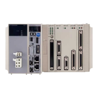
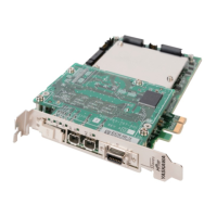
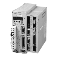
Do you have a question about the YASKAWA MP3300iec and is the answer not in the manual?
The Base Unit has two connectors: an RLYOUT connector and a power connector.
The RLYOUT connector outputs the status of the CPU Module.
Connect the power supply to this connector.
The specifications of the Communications Protocols built into the CPU Module are given in the following table.
The CPU Module has three types of connectors: MECHATROLINK-III, Ethernet, and USB.
The components that are used in the Machine Controller require the ambient operating temperature to be between 0 and 60 °C.
The SW1 and SW2 switches are checked at start-up, and their behavior is described in the following tables.
These indicators show the status of the CPU Module.
The controller can automatically configure all the Mechatrolink devices.
The Motion Works IEC (Express or Pro) configuration can detect the configuration and provide the user with configuration choices.
Cascaded connections allow you to connect one or more series of slave stations from the CPU Unit MECHATROLINK-III ports.
Star connections allow you to connect slave stations through Hub Modules. Each port on a Hub Module connects to only one slave station.
Modules are automatically synchronized when the power supply is cycled.
When the scan cycle is changed, MECHATROLINK communications with all slave stations connected to the SVC32 are reset.
The following table shows Servopacks that are compatible with MECHATROLINK-III and can be connected to the controller.
The following table shows the module that is compatible with MECHATROLINK-III and can be connected to the controller.
The operation of the RLY OUT connector is linked to the operation of the RDY indicator on the CPU Unit.
To connect the RLY OUT connector, use a cable with a wire size of AWG 28 to AWG 14 (0.08 to 2.0 mm²) and a maximum outer diameter of 3.4 mm.
The following table provides the Ethernet connector specifications.
For the Ethernet cable, use a twisted pair cable with RJ-45 connector. Yaskawa strongly recommends the use of shielded ethernet cables.
Illustrates the internal circuit configuration of the AI-01 Module for analog input channels.
The DO-01 module is equipped with 64 digital outputs.
Details the output circuit specifications of the DO-01 Module, including output format and voltage.
Shows the connector pin arrangement for LIO-01/02 Modules viewed from the wiring side.
Details the external I/O and encoder input connectors for the LIO-01/02 Modules.
Provides the hardware specifications for the LIO-04/05 Module, including digital inputs and outputs.
Details specifications for Digital Input, Digital Output, Analog Input, and Analog Output.
| Type | Motion Controller |
|---|---|
| Standard | IEC 61131-3 |
| Number of Control Axes | Up to 64 axes |
| Power Supply | 24 V DC |
| Operating Temperature | 0 to 55 °C |
| Protection Rating | IP20 |
| Programming Languages | LD, ST, FBD, SFC |
| Communication Interfaces | EtherCAT, USB |
| EtherCAT Cycle Time | 1 ms |
| Storage Temperature | -20 to 70 °C |
| Dimensions | 120 mm |
| Humidity | 10 to 95% RH (non-condensing) |


