4.4 Connecting an Incremental Encoder
4.4 Connecting an Incremental Encoder
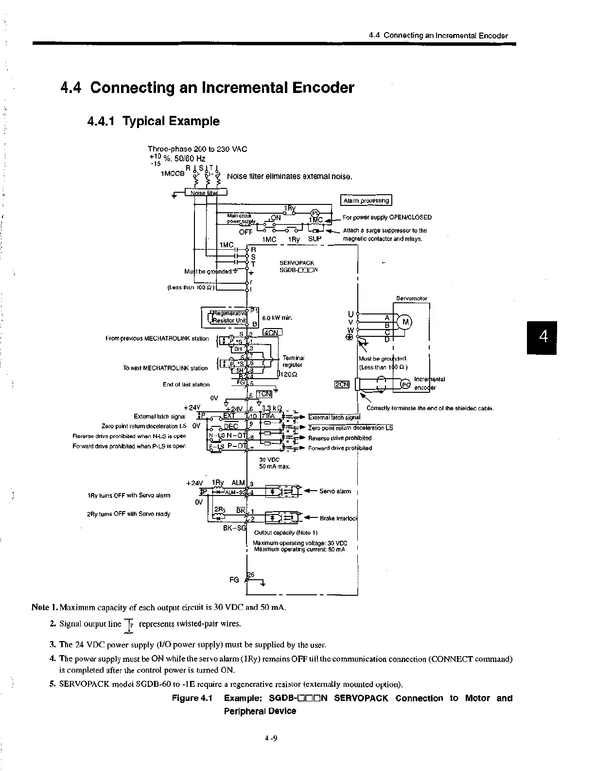
4.4.1 Typical Example
Three-phase 200 to 230 VAC
0
+1 %, 50/60 Hz
-15
1MCCBFlS1-1
Noise filter eliminates external noise.
1MO11_0R
1R
Alarm processing
Main cactia ON 1 For power supply OPEN/CLOSED
.power
OFF Attach a surge suppressor to the
1 MC 1 Ry SUP magnetic contactor and relays.
1-0 S
T
Must be gro
or
(Less than 100 )ot
+Regenerati7P P1
...r.fiesistor Unit B
From previous MECHATROLINK slat on { 9 ,:,7121.
YSH #3
{ It 9 u sPr79.6
To next MECHATROLINK station T SH1:8
R
End of last station
FG
OV
• V
+ 24\'+24V - ki2 _ External latch signal jj_.3 0- 0EXT 10 7mA
Zero point return deceleration LS OV —0 DEC
Reverse drive prohibited when N-LS is open
Forward drive prohibited when P-LS is open
SERVOPACK
SODS-000N
6.0 kW min.
4CN
Terminal
register
1200
1Ry turns OFF with Servo alarm
2Ry turns OFF with Servo ready
N- LS N-OT
1cm
1
P—
+24V 1Ry ALM 3
30 VDC
50 mA max.
OV
2Ry BK
BK-SG
Output capacity (Note 1)
Maximum operating voltage: 30 VDC
Maximum operating current: 50 mA
U
V
Servomotor
Must be gro ded.
(Less than 1 0 n )
1.111111CP enco.incre
ental
er
Correctly terminate the end of the shielded cable.
External latch signal
Zero point return deceleration LS
Reverse drive prohibited
Forward drive prohibited
FG
Servo alarm
Note 1. Maximum capacity of each output circuit is 30 VDC and 50 mA.
2. Signal output line I represents twisted-pair wires.
1 "I I - - Br ak e interloc
3. The 24 VDC power supply (I/O power supply) must be supplied by the user.
4. The power supply must be ON while the servo alarm (lRy) remains OFF till the communication connection (CONNECT command)
is completed after the control power is turned ON.
5. SERVOPACK model SGDB-60 to -1E require a regenerative resistor (externally mounted option).
Figure 4.1 Example: SGDB-01110N SERVOPACK Connection to Motor and
Peripheral Device
4 -9
 Loading...


