9.4 Connectors
Shell
Size
V Screw
95 A
B C
D
E
20
1 3/16-18UNEF-2A
37.3 ±0.8
(1.47 ± 0.0315)
60.5 ±0.8
(2.38 ± 0.0315)
74.2±0.8
(2.92 ± 0.0315)
32 ±0.8
(1.26 ± 0.0315)
10±0.5
(0.39 ± 0.0179)
22
1 3/16-18UNEF-2A
40.5 ±0.8
(1.59±0.0315)
60.23 ±0.8
(2.37±0.0315)
73.93±0.8
(2.91 ±0.0315)
32±0.8
(1.26±0.0315)
10±0.5
(0.39 ±0.0179)
24
1 7/16-18UNEF-2A 43.7±0.8
(1.72±0.0315)
65±0.8
(2.56±0.0315)
82±0.8
(3.23 ±0.0315)
38±0.8
(1.50±0.0315)
10±0.5
(0.39±0.0179)
Dimensions
Name
Dimensions
A±o.8
(A±0.031)
B±o•8
03±0.031)
C±o•8
(C-±-0.031)
D±O.8
(D-±0.031)
ct, E±O.3
(0E±0.011)
F
W screw Applicable Cable
Diameter
JL04-2022CK (14) 37.3
34.9 24.3 53.8 15.9
4 (0.16) 1 3/16-18UNEF-2B 0 12.9 to 0 15.9
(1.47)
(1.37) (0.96) (2.12) (0.63)
(0 0.51 to 0 0.63)
JL04-2428CK (17)
42.9 42.1 26.2 56.2
18 4.8 1 7/16-18UNEF-2B 0 15 to 0 18
(1.69) (1.66) (1.03)
(2.21) (0.71) (0.19)
(00.59 to 00.71)
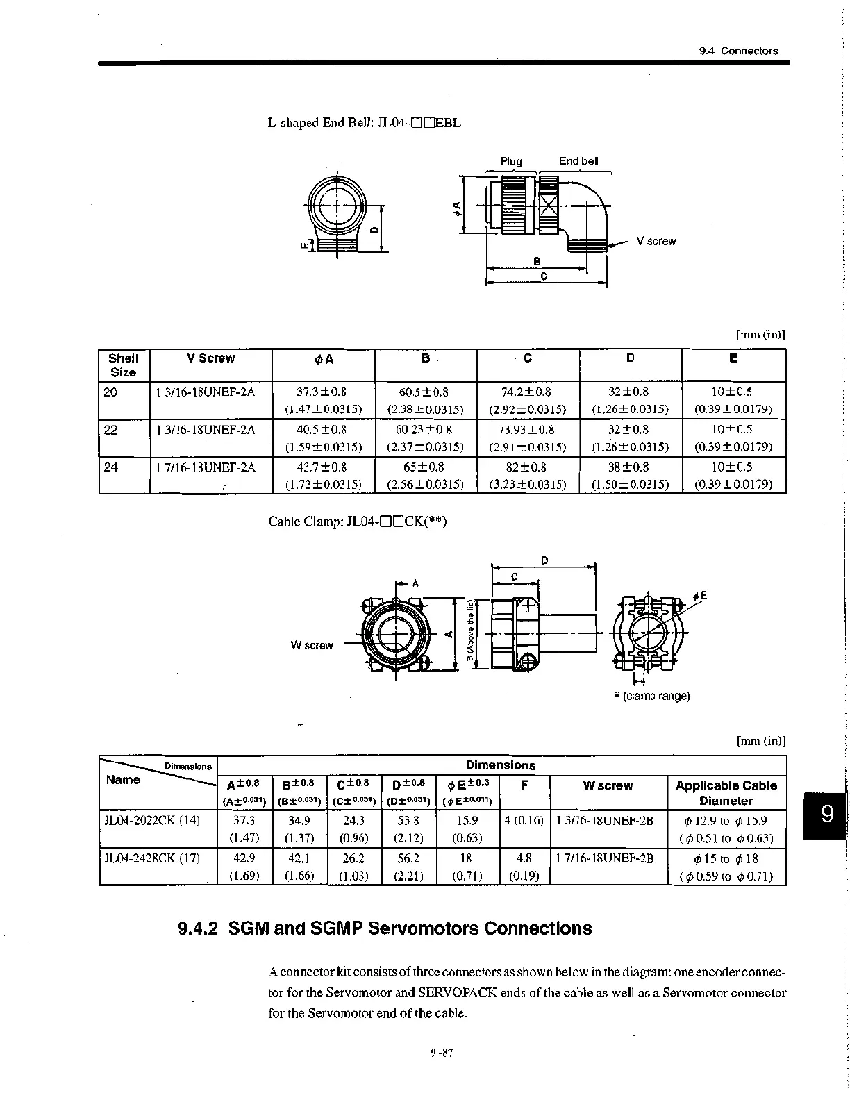
L-shaped End Bell: JL04-0111EBL
Plug
End bell
V screw
[mm (in)]
Cable Clamp: JL04-DOCK(**)
W screw
F (clamp range)
[mm (in)]
9.4.2 SGM and SGMP Servomotors Connections
A connector kit consists of three connectors as shown below in the diagram: one encoder connec-
tor for the Servomotor and SERVOPACK ends of the cable as well as a Servomotor connector
for the Servomotor end of the cable.
9 -87
 Loading...


