4.1 Internal Connection Diagram
4.1 Internal Connection Diagram
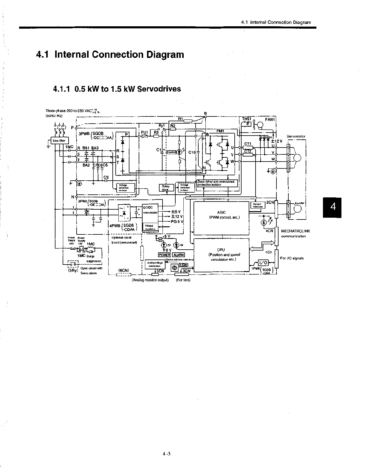
4.1.1 0.5 kW to 1.5 kW Servodrives
Three-phase 200 to 230 VAC*11°,,,..
(50/60 Hz)
)) cr
3PWB I SG1?CCi.,
Line filter
1 MC
—11
Fl BM BA3
S
BA2
T--- Ry1 R2 Tj
Ft_..,..11Z13
5'
5'
CeC5
C9
S
T
C1
PM1
'CHARGE
C10
P
N
V
THS1
FAN1
CT1
I
CT2
Servomotor
22 oar± 1
U
V
2V
Voltage
detection
isolator
2PWB (SGDB
Power Power
Supply Supply
OFF 014 1 MC
—L-
1 MC Surge
r =,--1 suppressor
L ----I Open circuit with
(5Ry)
Servo alarm
Relay
drive
Volt ge
date non
Isola or
pBraosieecdt iroivneirsaLdt isolator
e re urrent
4PWB (SGDB
-CDAA
1- Optional circuit
board (unmounted) I
DC/DC
conversion ±5 V
±12 V
PG 5V
Voltage
regulation
V
•0Vrr
IPOWERi
4-01
ASIC
(PWM control, etc.)
C rront
detection
2CN
I ALARM
(6CN) 15CN r3Z1,71
- --C • HI-- —I f— • —
(Analog monitor output) (For test)
Station address selection)
Analog voltage
01551:1
CPU
(Position and speed
calculation etc.)
()if
Encoder
_J
4CN MECHATROLINK
communication
1CN
I/O
1PWB SGDB
CAN
For I/O signals
 Loading...


